


– 23 –
THEORY OF OPERATION
Parallel Interface PCB Main PCB
DATA 1
DATA 2
DARA 3
DATA 4
DATA 5
DARA 6
DATA 7
DATA 8
STROBE
BUSY
ACK
ERROR
SELECTED
PAPER OUT
A4
B4
A5
B5
A6
B6
A7
B7
A13
A12
B12
A10
A11
B11
CN3
CPU
CN1
IC5
CN9
A4
B4
A5
B5
A6
B6
A7
B7
A13
A12
B12
A10
A11
B11
Gate array
IC10
LS05
IC1
CD0
CD1
CD2
CD3
CD4
CD5
CD6
CD7
CSTB
BUSY
ACK
ERROR
SELECT
POUT
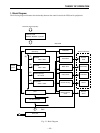
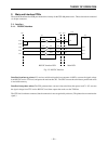
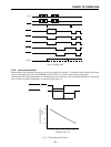
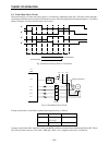
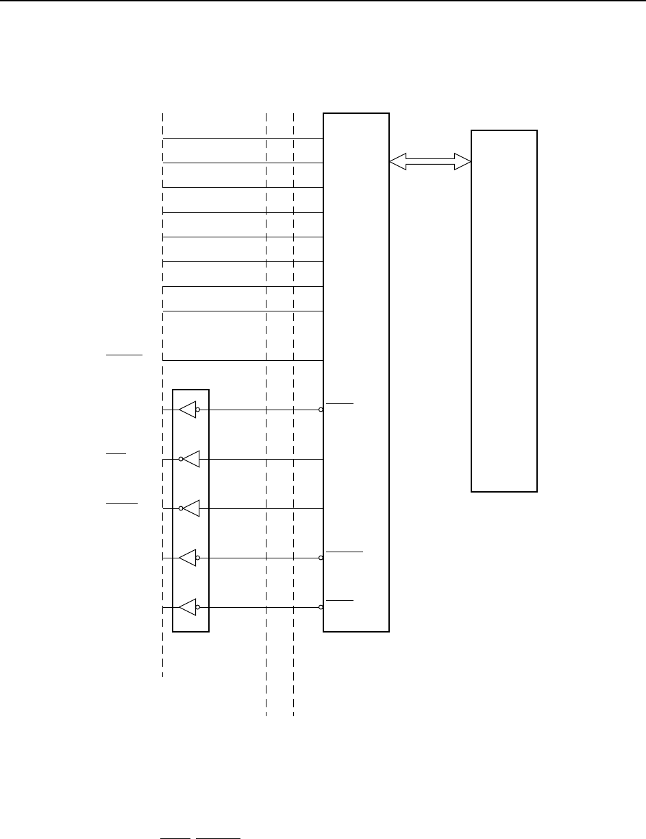
2-1-3. Parallel interface
Fig. 2-4 Parallel Interface
The host computer sends eight bits of parallel data to CN3 when the printer is ready (when BUSY is LOW).
The data passes through the interface PCB and gate array, then moves into the CPU.
Printer signals from the CPU (ACK, ERROR, SELECTED, PAPER OUT, etc.) pass through the gate array and are output
over the appropriate connector pins.