www.ti.com
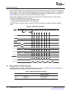
0 1 2 3 MBank 0
Row 0
Row 1
Row 2
Row N
C
o
l l
C
o
l
C
o
l
C
o
Row 0
Row N
Row 1
Row 2
CC
Bank 1
l l
0 21
oo
C C
l l
3 M
o o
Row 0
Row N
Row 1
Row 2
CC
Bank 2
l l
0 21
oo
llll
Row N
Row 2
Row 0
Row 1
Bank P 0 1 2 3 M
C C
l l
3 M
o o
o
C
o
C
o
C
o
C
2.7DDR2MemoryControllerInterface
PeripheralArchitecture
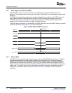
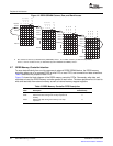
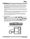
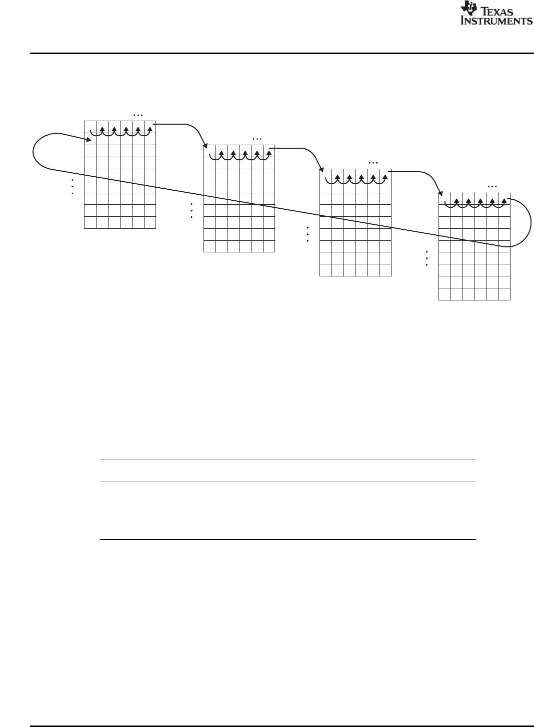
Figure14.DDR2SDRAMColumn,Row,andBankAccess
AMisnumberofcolumns(asdeterminedbyPAGESIZE)minus1,Pisnumberofbanks(asdeterminedbyIBANK)
minus1,andNisnumberofrows(asdeterminedbybothPAGESIZEandIBANK)minus1.
Tomovedataefficientlyfromon-chipresourcestoexternalDDR2SDRAMdevice,theDDR2memory
controllermakesuseofacommandFIFO,awriteFIFO,areadFIFO,andcommandanddataschedulers.
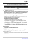
Table6describesthepurposeofeachFIFO.
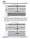
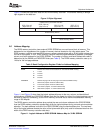
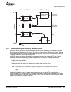
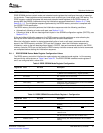
Figure15showstheblockdiagramoftheDDR2memorycontrollerFIFOs.Commands,writedata,and
readdataarriveattheDDR2memorycontrollerparalleltoeachother.Thesameperipheralbusisusedto
writeandreaddatafromexternalmemoryaswellasinternalmemory-mappedregisters.
Table6.DDR2MemoryControllerFIFODescription
Depth(64-Bit
FIFODescriptionDoublewords)
CommandStoresallcommandscomingfromon-chiprequesters7
WriteStoreswritedatacomingfromon-chiprequestersto11
memory
ReadStoresreaddatacomingfrommemorytoon-chip17
requesters
DSPDDR2MemoryController 22SPRUEK5A–October2007
SubmitDocumentationFeedback


