Section 3: Operation
013-100149-02 Rev. 1 (01/07) Christie DS+60/DW30/Matrix 3000 User’s Manual 3-47
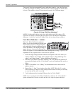
Peak Detector
The “Peak Detector” is a fast method for defining individual input levels, and can
improve the accuracy of input levels set by the Auto Input Level function. Enabling
the “Peak Detector” activates a special operating mode for detecting only pixels that
are considered black or white—all other levels are displayed as a mid-level gray.
When used with a 16-step grayscale pattern in which the two black and white bands
are known to be at opposite edges of the image, you can watch these isolated areas
while adjusting individual blacklevels and input drives until both bands are just
visible. Images from this source will then display correct blacks and whites without
crushing or washing out.
NOTE: If using Peak Detector with PIP, both images must have the same color space.
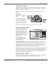
Level Detector
The “Level Detector” checkbox enables specific thresholds for blacks and whites—
input levels that fall below a specified Level Value (see below) are displayed as black,
and all others are displayed as white. It aids in Odd Pixel Adjustment. To use:
1. Enable “Level Detector” and display a continuous grayscale.
2. Set “Level Value” to near black (such as 200).
3. Adjust Offsets to minimize area of black stripe.
4. Set “Level Value” to near white (such as 800).
5. Adjust Gains to minimize area of white stripe.
Level Value
Level Value defines the value to be used by the Level Detector in recognizing blacks
and whites. See Level Detector, above.
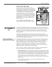
Aspect Ratio Overlay
Selecting this option with a checkmark will overlay a number of common aspect ratio
boxes on top of the source image. This is very helpful during the setup of the projector
and can be turned off after desired specifications have been achieved.
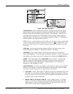
The single “Option Card” entry in the Configuration menu identifies which optional
input module (a.k.a. cards) is present at
INPUT 5 (Option 1). If the option slot is
empty, the corresponding read-only menu entry does nothing. If there is a module
installed, the corresponding menu entry may activate a submenu of further options
pertaining to that module.
For example, if the Dual SD/HD-SDI module is installed at
INPUT 5 (Option 1). The
Option 1 Card submenu provides controls for configuring the various connections on
this multi-input, multi-output module. As desired for your application, you can define
1) which physical input loops through to which output, and 2) which functional input
(main or PIP signal) loops through to which output.
System Configuration
f
OPTIONAL INPUT MODULES


