32
12.2 Key-Switch and Buttons
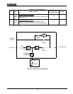
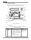
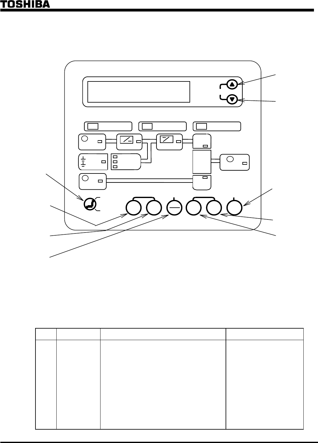
The key-switch and operating buttons on the graphic panel are shown in Figure 10. See
the sections titled "Key-switch" and "Operating buttons" for each function.
Figure 10 - Graphic Panel.
12.2.1 Key-switch
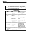
Table 6 shows the function of the key-switch on the graphic panel.
Table 6 - Key-switch function.
No. Name Function Remarks
OPERATION
LOCK
This key-switch enables operation buttons
pressed when it is in "OPERATION" mode.
When the key-switch is at "OPERATION
INHIBITED" mode, the operation is disabled,
and buttons ~ and shown in Table 7
are not operative. They have no effect upon
the UPS operation.
LCD scroll buttons and still work
regardless of the key-switch position.
The key-switch at the
“OPERATION INHIBITED"
can eliminate misoperation
procedures.
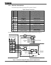
SCROLL
UPS SUPPLY
WARNING
FAULT
OPERATION
OPERATION
INHIBITED
RUN
STOP
UPS
EQUAL
FLOAT
CHARGE
AC SWITCH
FAULT
BYPASS
UPS
RESET
AC OUTPUT
AC
SWITCH
AC INPUT
CONVERTER
~
INVERTER
~
BATTERIES
DISCHARGE
FLOAT CHARGE
EQUAL CHARGE
UPS
BYPASS
BYPASS INPUT


