38
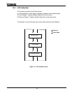
13.2.1 Normal Display
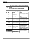
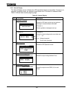
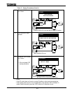
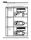
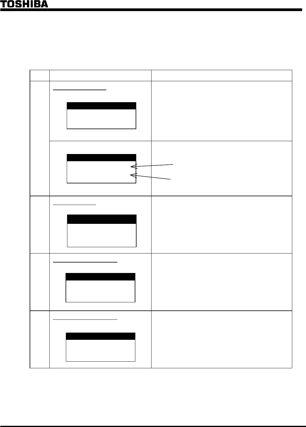
The Normal Display screen indicates the UPS operational status and provides 15 screens: an
operation guidance screen, an operation mode screen and 13 screens of measured data.
Table 10 shows these screens page by page.
Table 10 - Normal Display.
No. LCD Screen Description
1 Operation Guidance
(Example 1)
Shows the UPS status at the top and guidance
message or measured data underneath.
(Example 1)
Shows a guidance message at start up.
(Example 2) (Example 2)
Shows the output voltage and current after start
up.
Voltage (example)
Current ratio (example)
2
Operation Mode
(Example)
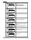
Shows the UPS Operation mode.
3 Measurement screen #1
Output voltage
Shows the output voltage between lines.
4 Measurement screen #2
Output current (RMS)
Shows the output current RMS (%) for each
phase.
BYPASS
PRESS ‘RUN’ SWITCH
O/P VOLTAGE
VOLT. 480[V]
FREQ. 60.0[Hz]
O/P CURRENT (r.m.s)
U 50[%]
V 50[%]
W 50[%]
UPS SUPPLY
AC-VO 480[V]
AC- I O 50[%]
OPERATION MODE
NORMAL OPERATION MODE
SYNC.


