


54
15.2.3 Fault Messages
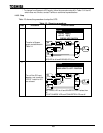
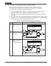
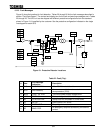
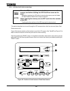
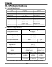
Figure 19 show the locations for fault detection. Tables 22 through 26 list the fault messages described in
section
"Fault Data Screen." The content and display text for the fault and warning messages are in Tables
22 through 26. The UPS unit can be shipped with different protective configurations from the standard
shown in Figure 19, if specified by the customer. See the protective configuration indicated on the single
line diagram for each UPS.
Figure 19 - Protective Detector Locations.
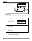
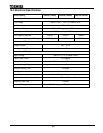
Table 22 - Fault (Trip).
# Item
LCD Message
Indication
Description
1 71F FUSE BLOWN AC or DC Main circuit fuse blown.
2 30ST (No indication)
An error occurred in the main control
microprocessor (CPU).
3 80PS CONT. PS. ERR The control power supply voltage failed.
4 80B2 BATT. UV Battery voltage is below cutoff voltage.
5 48 STARTUP ERR Startup was not completed in a time frame.
6 76 DC OC Over-current in DC circuit.
7 26 OVER HEAT Temp High in the cabinet.
8 5E EMG.STOP
An emergency stop was activated by the external
contact.
95S
27S
59S
52R
30U
71F
76C
80B1
80B2
INVERTER
47C
59C
27C
45
51I
59I
27I
49
5E
80PS
30ST
UPS
47S
26B
95C
48
76
26
Chopper
83MC1
83MC2
83BF