


1
5
9
3
7
11
2
6
10
4
8
12
13
14
11
6 – Wiring
DANGER! LETHAL HIGH VOLTAGE HAZARD!
All wiring should be performed by a qualified electrician in accordance with the warnings in this manual, all applicable
electrical and safety codes, and good wiring practices. Incorrect wiring may damage the UPS system severely and cause
serious personal injury and property damage. Read Section 2 – Important Safety Instructions before proceeding.
6-1 Wiring Warnings
• De-energize all input and output power sources of the UPS system before installing cables or making electrical connections.
• Use flexible cable of sufficient length to permit UPS system servicing. The maximum cable length is 10 m (32.8 ft).
• Use ferrule caps to cover termination cables within mechanical lugs, or use compression lugs in order to prevent frayed ends from shorting on
the UPS system terminal block.
• Use cabling rated VW-1, FT-1 or better.
• Use cable sleeves and connector clamps.
• The neutral conductor must be the same size as the current conductors.
• Tighten all field wiring terminal connections with a torque of at least 3.95 N·m (35 in·lb); a torque of 11.8 N·m (100 in·lb) is required for the
“In”, “Out” and “Battery” bolt-screw terminals.
• Confirm that all cables are marked correctly according to their purpose, polarity, phase and diameter.
• If the UPS system’s input/output power source is wye-wye, then “Neutral” and “Ground” must not be re-bonded at the UPS.
• If the input power source has VNG>0, install a grounded wye secondary isolation transformer with a properly bonded neutral to ground before
the UPS system and input power source.
• For equipment requiring a neutral connection to an IT power distribution system that requires neutral isolation upon disconnect, the disconnect
device must be a four-pole device and must disconnect all line conductors and the neutral conductor. If a disconnect device interrupts the neutral
conductor, it must simultaneously interrupt all line conductors.
• Allow the batteries to charge uninterrupted for 24 hours after the initial wiring connection and UPS startup.
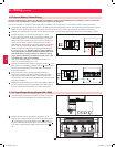
• Observe proper polarity by connecting negative to negative, positive to positive and the center point of the battery string to the normal “N”
terminal. Do not bond the battery’s “N” terminal to the AC power “Neutral” or “Ground” as damage may result. Failure to observe proper
polarity will damage the UPS system and create a serious risk of personal injury and property damage.
• Observe proper phase by connecting R to R, S to S, T to T and N to N. Source power phase rotation must be verified as RST before powering
the UPS. Failure to observe proper phase will damage the UPS system and create a risk of personal injury and property damage.
6-2 Wiring Preparation
• De-energize all input and output (AC and DC) of the UPS system and external battery cabinet (if present).
• Mark all cables according to their correct purpose, polarity, phase and diameter.
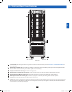
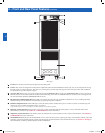
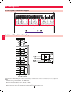
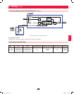
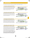
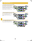
• Review the diagrams in Section 6-3 and Section 6-4 to familiarize yourself with the terminal blocks.
• Consult the table in Section 6-5 to find the correct electrical input/output characteristics for the UPS system.
Note: If the UPS system’s input/output power source is wye-wye, then “Neutral” and “Ground” must not be re-bonded at the UPS. If the input
power source has VNG>0, install an isolation transformer as part of the UPS input power source and bond “Neutral” and “Ground” together at
the isolation transformer’s output.
12-212-93-3141.indb 11 12/28/2012 11:17:22 AM