


1
5
9
3
7
11
2
6
10
4
8
12
13
14
4
3
1
2
Q4 Q2 Q1Q3
A
B
14
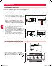
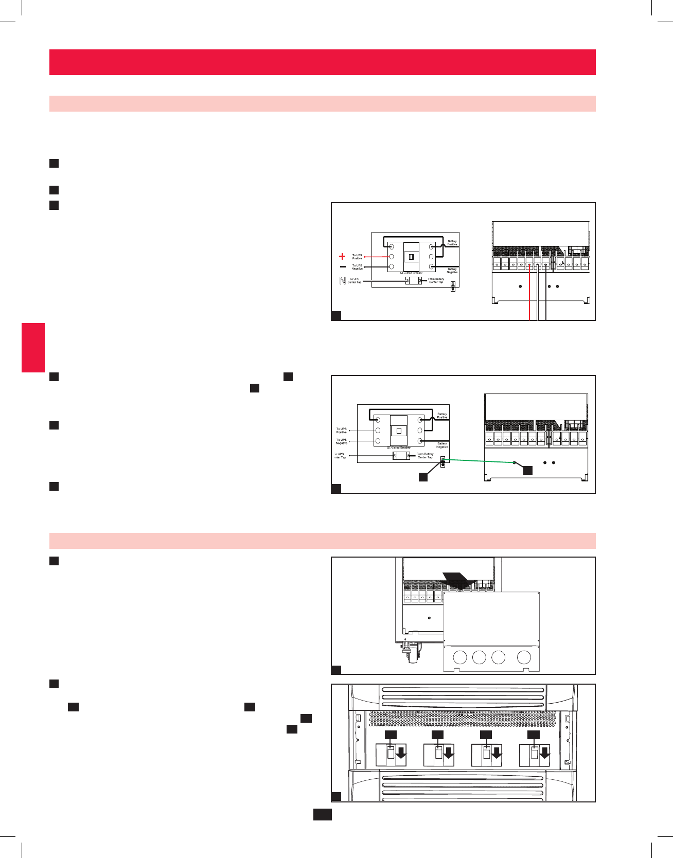
6 – Wiring (continued)
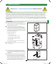
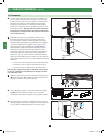
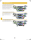
6-6 External Battery Cabinet Wiring
Warning: External battery cabinets vary. Read the external battery cabinet’s documentation before attempting to connect it to the UPS
system. Use only external battery cabinets that have been approved by Tripp Lite.
Note: An external battery cabinet is required with model SU120KX2. Contact Tripp Lite for external battery cabinet ordering information.
• De-energize all input and output (AC and DC) of the UPS system and external battery cabinet, and confirm that the external battery cabinet
breaker switch
is off. (If the UPS system has already been wired to an AC power source, see Section 8-6 for shutdown instructions.)
• Remove the terminal block covers from the UPS. Remove the front cover and conduit plates (if provided) of the external battery cabinet.
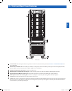
• Connect the positive (+), normal (N) and negative (-) UPS
system connection terminals of the external battery cabinet to the
corresponding positive (+), normal (N) and negative (-) external
battery connection terminals of the UPS system. See Section 6-3
and the external battery cabinet’s documentation for terminal
block diagrams. See Section 6-4 for wiring diagrams. See Section
6-5 for cable size requirements. Cabling should be protected by
flexible conduit and routed through the appropriate knockouts in
the terminal block cover. Warning: Observe proper polarity by
connecting negative to negative, positive to positive and center
point of the battery string to normal “N”. Failure to observe
proper polarity will damage the UPS system and create a risk
of personal injury and property damage.
Note: Do not bond the battery “N” terminal to the AC power
neutral or ground as damage may result.
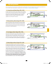
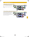
• Connect the external battery cabinet’s grounding terminal
A
to the
UPS system’s corresponding grounding terminal
B
with a 4 AWG
(25 mm²) ground cable. Keep the ground cable connected at all
times after installation.
• Connect the UPS system’s primary grounding terminal
to
your facility’s earth ground
with a 4 AWG (25 mm²) minimum
equipment grounding conductor (EGC) cable within the same
conduit used in item 3 above. Keep the EGC cable connected at all
times after installation.
• Replace the conduit landing cover of the external battery cabinet. If
you do not plan to wire the AC input/output of the UPS system at
this time, replace the terminal block cover of the UPS system.
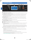
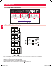
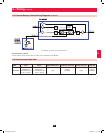
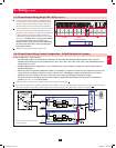
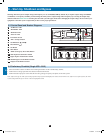
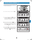
6-7 AC Input/Output Wiring (Single UPS—SUS)
• After de-energizing all input and output (AC and DC) of the UPS
system, remove the terminal block cover from the UPS system.
• Remove the UPS system’s front bezel to expose the circuit
breakers. First, confirm that the main input circuit breaker switch
Q1
and the bypass input circuit breaker switch
Q2
are both off.
Second, confirm that the manual bypass circuit breaker switch
Q3
is off. Third, confirm that the output circuit breaker switch
Q4
is
off.
1
2
3
4
5
6
1
2
12-212-93-3141.indb 14 12/28/2012 11:17:25 AM