


1
5
9
3
7
11
2
6
10
4
8
12
13
14
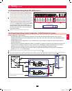
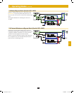
3-8
6 5 7 3
Output Manual
Bypass
Bypass
Input
Main
Input
Q3 Q1Q4 Q2
1
3
6
5
7
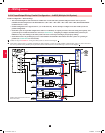
Output Manual
Bypass
Bypass
Input
Main
Input
Q4 Q3 Q2 Q1
Q2
Q3
Q4
Q1
23
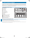
8 – Start-Up, Shutdown and Bypass (continued)
3
4
5
6
7
8
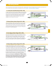
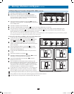
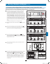
To transfer the critical load to NORMAL mode from Manual Bypass mode:
1. Confirm the UPS is in MANUAL BYPASS (the MANUAL
BYPASS circuit breaker
Q3
is ON; the OUTPUT
Q4
, BYPASS
INPUT
Q2
and MAIN INPUT
Q1
circuit breakers are OFF).
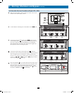
2. Turn ON the BATTERY BREAKER. For the external battery
cabinets, the BATTERY BREAKER will be behind the front door/
panel or elsewhere.
3. Turn ON the BYPASS INPUT circuit breaker
Q2
(the amber
Bypass LED should come on and the LCD will display “Load
Unprotected-On Manual Bypass).
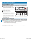
4. Confirm the amber BYPASS LED is ON. Do not proceed if it is
not ON.
5. Turn ON the OUTPUT circuit breaker
Q4
.
6. Turn OFF the MANUAL BYPASS circuit breaker
Q3
. The LCD
will display “Load Unprotected-On Auto Bypass”.
7. Turn ON the MAIN INPUT circuit breaker
Q1
. The Power
Module fans will turn ON.
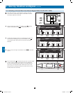
8. Press and hold the green ON button until the UPS beeps, then
release the button. The UPS will perform a self-test diagnostic and
the LCD will display “Self Diagnosis”. After the UPS self-test is
completed, the UPS will transfer to NORMAL mode (green LED
ON and LCD displays “Load Protected-On Line Mode”).
9. Confirm there are no active alarms present (“!” on the display and
audible beeping). If an alarm is present, press the UP or DOWN
arrows to display the active alarm. Correct the action as required.
10. Scroll through the Measure Menu and confirm all input and output power readings are within the recommended specifications.
11. If any problems are noted, contact your technical support personnel for further assistance.
12. The critical load is now supported by conditioned battery back-up power.
1
2
3
4
5
6
7
8
9
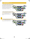
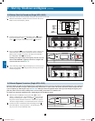
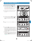
8-5 Manual Bypass Procedure (Single UPS—SUS) (continued)
• Turn OFF the MAIN INPUT circuit breaker
Q1
.
• Wait until the Power Module fans turn OFF (this may take a
minute or two), then turn OFF the BATTERY BREAKER. Note:
The external battery cabinets will have the BATTERY BREAKER
behind the front door/panel or elsewhere.
• Turn ON the MANUAL BYPASS circuit breaker
Q3
. The LCD
will display “Load Unprotected – On Manual Bypass” and you will
hear an audible alarm.
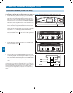
• Turn OFF the OUTPUT circuit breaker
Q4
.
• Turn OFF the BYPASS INPUT circuit breaker
Q2
. The unit’s LCD will go blank after a few seconds.
• The critical load is now supported by unconditioned utility power in manual bypass mode. In this mode, only the manual bypass path
(including manual bypass breaker
Q3
), the load terminals of the output breaker
Q4
] and the terminal block contain hazardous voltage,
allowing qualified service personnel to perform maintenance or repair.
Note: Use of an external 3-breaker maintenance bypass panel is recommended if the connected equipment is to be powered during complete
de-energized maintenance or repair/service procedures on the UPS system.
10
11
12
12-212-93-3141.indb 23 12/28/2012 11:17:34 AM