


1
5
9
3
7
11
2
6
10
4
8
12
13
14
1
2
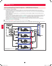
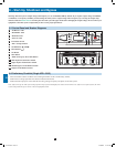
B
Output Manual
Bypass
Bypass
Input
Main
Input
3 5 4
Q3 Q1Q4 Q2
A
C
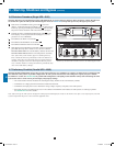
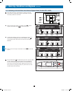
Position of circuit breaker switches shown as in manual bypass mode.
24
8 – Start-Up, Shutdown and Bypass (continued)
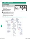
8-7 Preliminary Checklist (Parallel UPS—MUS)
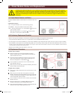
Warning: Parallel configurations of two, three or four UPS systems (for N+1 redundancy or capacity) are allowed. Do not attempt to link
more than four UPS systems via parallel configuration. All UPS systems must have the same rating, kVA capacity and power module
level firmware version (See Section 10-6) for parallel UPS configuration. Attempting to link dissimilar UPS systems will damage the UPS
systems and create a serious risk of personal injury and property damage.
• All circuit breaker switches should be off, including the battery breakers of the external battery cabinets.
• Confirm that no voltage potential exists between Neutral and Ground.
• Confirm that the input power source matches the rating (voltage, frequency and phase) of the UPS systems.
• Each UPS must have its parallel group set to 2 and a different “Parallel ID” that indicates the UPS systems are running in parallel.
See Section 10-5-5 for more details.
Note: After start-up, the UPS systems will perform a brief self-test and display the results on the LCD screen. After a successful self-test, the UPS
systems will provide AC power to the connected equipment load.
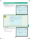
8-6 Shutdown Procedure (Single UPS—SUS)
Warning: The UPS system shutdown procedure will eliminate the AC power output for all loads. Before shutdown, confirm that all loads
are turned off or place the UPS system in manual bypass mode (See Section 8-5) to keep loads powered by the bypass power path.
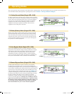
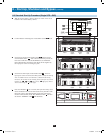
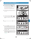
• If the UPS is in NORMAL mode (green LED
A
ON, LCD
displays “Load Protected-On Line Mode”), then you must stop the
inverter by pressing and holding the OFF button
B
until the UPS
beeps, then release the button. The UPS will transfer to Bypass.
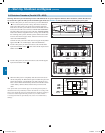
• Confirm the UPS is in BYPASS (amber Bypass LED
C
is ON;
LCD displays “Load Unprotected-On Auto Bypass”). Do not
proceed if it is not on BYPASS.
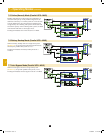
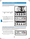
• Turn OFF the OUTPUT circuit breaker
Q4
.
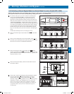
• Turn OFF the MAIN INPUT circuit breaker
Q1
.
• Turn OFF the BYPASS UNIT circuit breaker
Q2
.
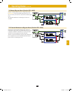
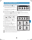
• Wait until the Power Module fans turn OFF and the LCD display
goes blank (this may take a minute or two), then turn OFF the
BATTERY BREAKER. The external battery cabinets will have the
BATTERY BREAKER behind the front door/panel or elsewhere.
Note: If the UPS system remains off for an extended period of
time, it should be turned on periodically to allow the batteries to
recharge. The UPS system should be turned on and the batteries
should be recharged at least one uninterrupted 24-hour period
every 3 months. Failure to recharge the batteries periodically may
cause irreversible battery damage.
1
2
3
4
5
6
12-212-93-3141.indb 24 12/28/2012 11:17:35 AM