


1
5
9
3
7
11
2
6
10
4
8
12
13
14
DC
P1
USER-SUPPLIED
REPO - N.O. LATCHING SWITCH
DC
DC
P2
USER-SUPPLIED
INPUT N.O. CONTACTS
INPUT
DRY A
INPUT
DRY B
53
11 – Communications (continued)
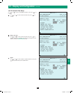
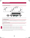
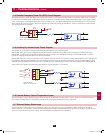
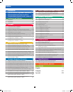
11-4 Remote Emergency Power Off (EPO) Circuit Diagram
The Remote Emergency Power Off (EPO) input connection (P1) allows you to connect the UPS system to your facility’s EPO circuit. Connecting
the UPS system to the EPO circuit enables remote emergency shutdown of the UPS system’s output. Connect EPO input to a user-supplied remote
switch, following the circuit diagram below. This contact is normally open. User supplied REPO button must be latching type in a closed position.
When opened, the UPS goes to bypass. The inverter must then be restarted by pressing the ON button to return to on-line mode. Contact rated for
12V DC minimum, 0.1A (nominal).
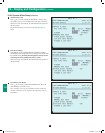
11-5 Auxiliary Dry Contact Input Circuit Diagram
The auxiliary dry contact input connections (P2) allow the UPS system to receive external signals.
INPUT DRY A (P2, pins 1 and 2) is utilized with generator controls. If required, as the generator starts up, closing the normally open (N.O.)
INPUT DRY A contact will cause the UPS to limit the DC charging current to less than half of its settings. Once the INPUT DRY A contact is
opened, DC charging current will return to its normal set functions.
INPUT DRY B (P2, pins 3 and 4) is utilized for remote shutdown within 60 seconds of its activation. Closing INPUT DRY B contact will begin the
UPS shutdown. Opening INPUT DRY B contact will disable the shutdown sequence. Repeated open/close sequencing of INPUT DRY B contact
should be avoided as damage to the UPS may result. A normally open (N.O.) latching type contact is therefore recommended for INPUT DRY B.
These contacts are normally open. External contacts rated for 12V DC minimum, 0.1A (nominal).
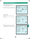
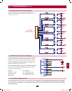
11-6 External Battery Cabinet Temperature Inputs
The external battery cabinet temperature input connections (P3, P4, P5, P6) allow the UPS system to receive signals from an optional accessory
that monitors the temperature of external battery cabinets. Visit www.tripplite.com/support for more information.
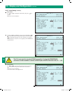
11-7 External Battery Status Input
The external battery cabinet status input connection (P7) allows the UPS system to receive external battery cabinet status signals through an
optional cable. Pin 1 = +12V; Pin 2 = detection cable connected; Pin 3 = battery cabinet breaker status (signal active= breaker on; signal inactive =
off); Pin 4 = reserved; Pin 5 = reference voltage. Visit www.tripplite.com/support for more information.
12-212-93-3141.indb 53 12/28/2012 11:18:15 AM