


1
5
9
3
7
11
2
6
10
4
8
12
13
14
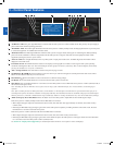
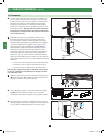
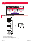
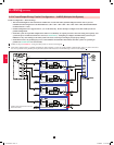
AC Input Battery Output
Grounding Terminals
R RS ST TN NN
+
–
12
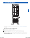
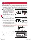
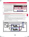
6 – Wiring (continued)
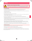
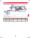
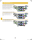
Battery and Circuit Breaker Diagram shown for illustration only; consult the battery cabinet’s documentation for exact specifications.
Notes:
• All internal wiring is UL-listed, MTW, 125C Hi-Flex cable.
• Terminal block is UL-recognized and rated for 600 VDC.
• Breaker is UL-listed and rated for 250 A, 600 VDC, 25 KAIC.
• Cabinets with breakers are shipped with the breaker in the off/open position.
• Battery arrangements shown are typical but may vary depending on cabinet and battery type.
6-3 UPS System Terminal Block Diagram
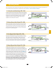
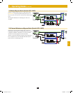
6-4 External Battery Cabinet Wiring Diagrams
12-212-93-3141.indb 12 12/28/2012 11:17:22 AM