


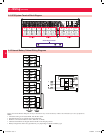
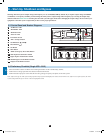

1
5
9
3
7
11
2
6
10
4
8
12
13
14
1
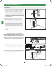
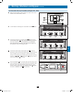
DASHED LINES INDICATE USER-SUPPLIED
PARTS AND CABLES.
16
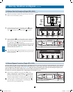
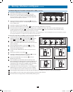
6 – Wiring (continued)
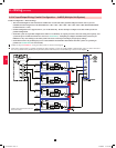
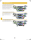
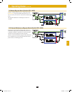
6-9 AC Input/Output Wiring: Parallel Configuration – 4x MUS (Multiple Unit System)
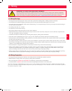
Parallel Configuration – MUS Warnings:
• The total cable length for each UPS must be within 10% of each of the other parallel-configured UPS in order to prevent
unbalanced load sharing between the individual UPS. (IP1 + OP1 = IP2 + OP2 = IP3 + OP3 = IP4 + OP4, minimum/maximum
deviation must be < 10%).
• Parallel configurations are supported for 2, 3, or 4 UPS units only. Do not attempt to configure more than 4 UPS systems via
parallel configuration.
• Each UPS system to be parallel configured for either N+1 redundancy or capacity, must have the same rating, kVA capacity, and
system and power module level firmware version (see Section 10-6). Attempting to configure dissimilar UPS systems may be
inhibited or may cause damage to the UPS systems and create a risk of personal injury and property damage.
• Each UPS must have its parallel group set to 2 and a different “Parallel ID” that indicates the UPS systems are operating in
parallel (see Section 10-5-5 for more details).
• Follow the steps in Section 6-7, wiring the UPS systems as shown in the diagram
1
.
• Each UPS is shipped with (1) parallel configuration cable included. Connect each UPS parallel communication port(s) as shown and select
the correct position of the parallel port dip switches (either both ON (down) or both OFF (up) as shown in the diagram
1
.
1
2
12-212-93-3141.indb 16 12/28/2012 11:17:26 AM