


1
5
9
3
7
11
2
6
10
4
8
12
13
14
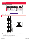
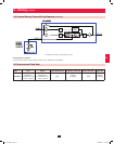
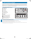
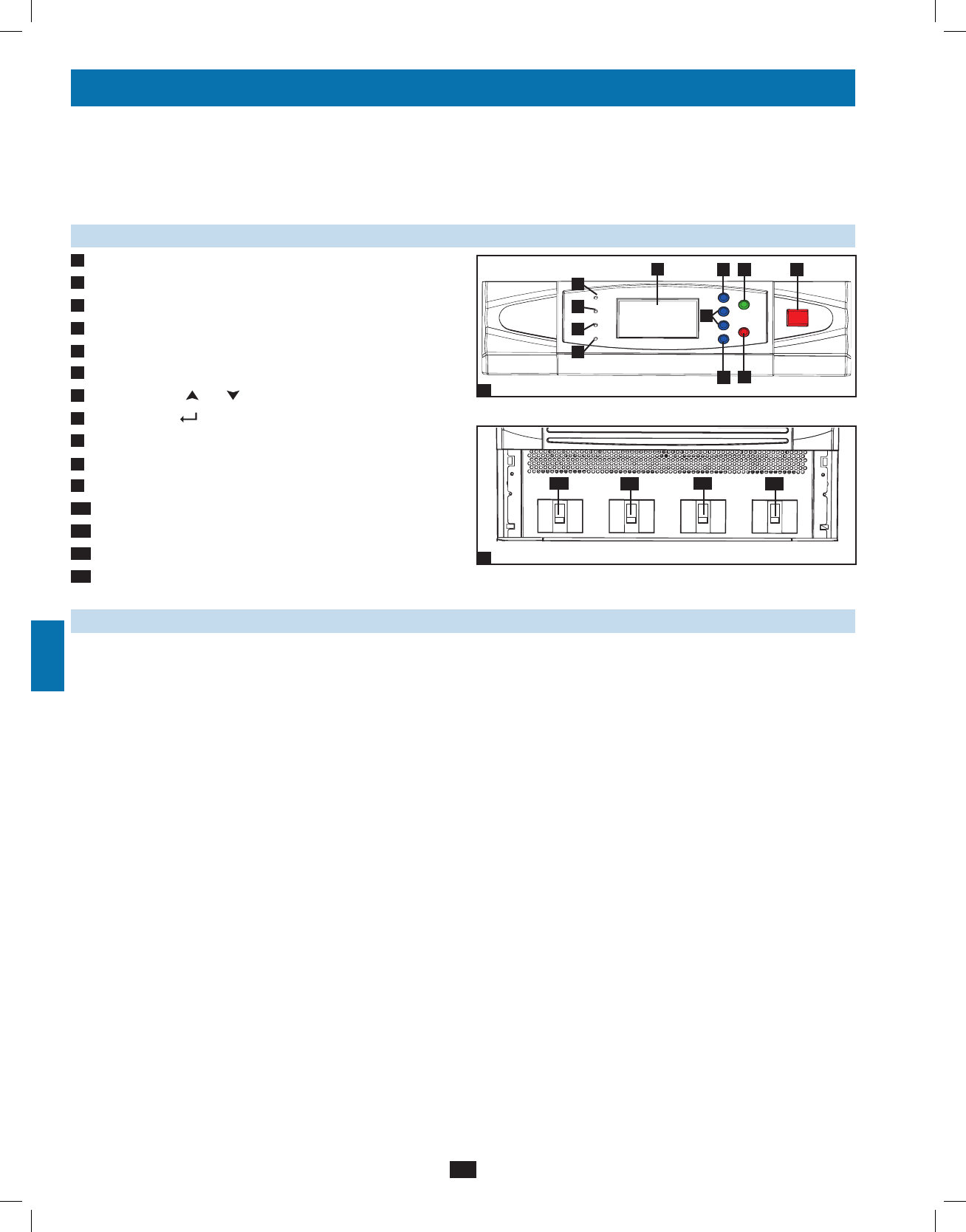
Control Panel
Circuit Breaker Switches (UPS System Front Panel)
1
2
E
F
G
K
A
B
C
D
H
I
J
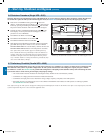
Q4
Q3
Q2
Q1
Output Manual
Bypass
Bypass
Input
Main
Input
20
8 – Start-Up, Shutdown and Bypass
Warning: The UPS system’s output voltage and frequency are set at 220/380V, 50Hz by default. If you require output voltage of 230/400V
or 240/415V, or a frequency of 60Hz, you must change the UPS system’s output voltage and/or frequency by accessing the output setup
menu described in Section 10-5-2. You must place the UPS system in bypass mode before changing the output voltage. Do not connect your
equipment to the UPS system’s output until you have set the proper parameters.
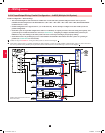
8-1 Control Panel and Breaker Diagrams
• “NORMAL” LED
• “BATTERY” LED
• “BYPASS” LED
• “FAULT” LED
• LCD Status Screen
• “ESC” (Escape) Button
• Scroll Buttons ( and )
• Enter Button ( )
• ON Button
• OFF Button
• “EPO” (Emergency Power Off) Button
• Main Input Circuit Breaker Switch
• Bypass Input Circuit Breaker Switch
• Manual Bypass Circuit Breaker Switch
• Output Circuit Breaker Switch
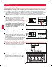
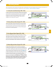
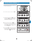
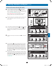
8-2 Preliminary Checklist (Single UPS—SUS)
• All circuit breaker switches should be off, including the breaker of the external battery cabinet.
• Confirm that no voltage potential exists between Neutral and Ground.
• Confirm that the input power source matches the rating (voltage, frequency and phase) of the UPS system.
Note: After start-up, the UPS system will perform a brief self-test and display the results on the LCD screen. After a successful self-test, the UPS
system will provide AC power to the connected equipment load.
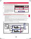
A
B
C
D
E
F
G
H
I
J
K
Q1
Q2
Q3
Q4
12-212-93-3141.indb 20 12/28/2012 11:17:30 AM