


1
5
9
3
7
11
2
6
10
4
8
12
13
14
Q2
Q3
Q1
STS
Q4
FB
FB
FB
6 X 20KVA MODULES
3 PH, 4W + G
POS, NEG, N + G
3 PH, 4W + G
IN
OUT
EXT BATT
PARALLEL
PORTS
CLOSED
CLOSED
CLOSED
OPEN
CLOSED
STS
FB
FB
17
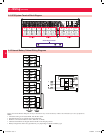
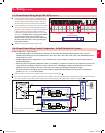
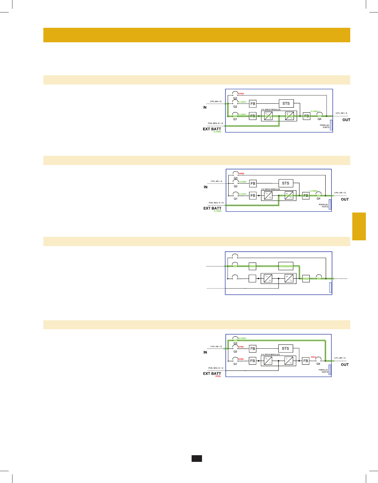
7 – Operating Modes
This section provides a basic description of the UPS system’s operating modes. The one-line diagrams used are schematic representations. For
more information about switching between operating modes, refer to Section 8 – Start-Up, Shutdown and Bypass.
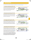
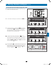
7-1 Online (Normal) Mode (Single UPS—SUS)
In online (normal) mode, the UPS system’s rectifier converts incoming
AC utility power to DC power that charges the batteries and supplies the
inverter. The inverter transforms the DC power to precision-regulated,
pure sine wave AC power that supports the operation of connected
equipment. This dual conversion technology isolates connected
equipment from all power problems and ensures that connected
equipment receives ideal power at all times.
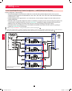
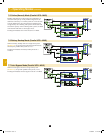
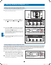
7-2 Battery Backup Mode (Single UPS—SUS)
When a power outage or other extreme power event occurs, the UPS
system automatically switches from normal mode to battery backup
mode. The UPS system’s batteries (internal and/or external) provide
emergency DC power to the inverter. The inverter transforms the DC
power to precision-regulated, pure sine wave AC power that supports
the operation of connected equipment.
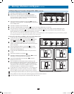
7-3 Auto Bypass Mode (Single UPS—SUS)
If the inverter malfunctions due to excessive temperature, overload,
output short circuit, abnormal voltage or battery problems, the inverter
will shut down. If the UPS system detects a bypass (reserve) power
source that conforms to normal parameters, then the UPS system
automatically switches to auto bypass mode to continue supplying
power to connected equipment. When all problems are eliminated, the
UPS system switches back to online (normal) mode automatically.
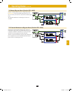
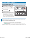
7-4 Manual Bypass Mode (Single UPS—SUS)
If UPS system maintenance or repair is required, you can bypass
the UPS system and enable bypass (reserve) power manually. After
confirming that the bypass source is present (input AC available and Q3
open), transfer to manual bypass mode by first pressing the off button to
stop the inverter. This transfers the UPS to static internal bypass. Next,
switch the UPS system into manual bypass mode. (See Section 8-5 for
complete manual bypass procedure.) The one-line diagram illustrates
the system status and flow of power after the manual bypass procedure
has been completed. This allows service technicians to perform
maintenance or repair procedures without interrupting the flow of AC
power to connected equipment. Warning: After switching to manual
bypass mode to perform selected maintenance or repair procedures,
the UPS may require complete shutdown to affect those repairs. Use
of an external 3-breaker maintenance bypass panel can facilitate
this and still maintain AC power to the connected equipment.
12-212-93-3141.indb 17 12/28/2012 11:17:27 AM