


1
5
9
3
7
11
2
6
10
4
8
12
13
14
A
B
C
G
G
H H
F
D E
7
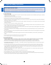
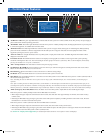
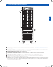
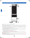
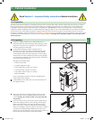
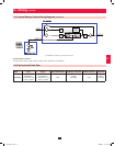
4 – Front and Rear Panel Features
• Control Panel: The control panel allows the operator to monitor and control the UPS system. See Section 3 – Control Panel Features for
more information.
• Internal Power Modules: 20kVA internal power modules can be replaced in the field without powering down connected equipment loads.
The SU120KX2 contains 6 internal power modules capable of N+1 redundancy.
• Output Circuit Breaker Switch (Q4): Controls AC output power.
• Manual Bypass Circuit Breaker Switch (Q3): Controls AC input power to the UPS system during manual bypass operation.
• Bypass Input Circuit Breaker Switch (Q2): Controls AC input power to the UPS system during auto bypass operation.
• Main Input Circuit Breaker Switch (Q1): Controls AC input power to the UPS system during online (normal) operation.
• Levelers: The levelers provide long-term support for the UPS system.
• Casters: The casters are designed for small position adjustments within the final installation location only; they are not designed for moving
the UPS system over longer distances. The casters are not designed to provide long-term support for the UPS system after final installation.
Use the levelers to provide long-term support.
A
B
C
D
E
F
G
H
Front View
12-212-93-3141.indb 7 12/28/2012 11:16:56 AM