


1
5
9
3
7
11
2
6
10
4
8
12
13
14
5
1
2
3
4
A
Output
Output
Output
Manual
Bypass
Manual
Bypass
Manual
Bypass
Bypass
Input
Bypass
Input
Bypass
Input
Main
Input
Main
Input
Main
Input
Q1
Q3
Q2Q4
6
Q4 Q3
B
27
8 – Start-Up, Shutdown and Bypass (continued)
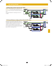
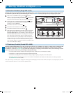
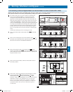
8-10 Switching to Manual Bypass Mode from Normal Mode Procedure (Parallel UPS—MUS)
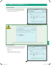
Warning: When the UPS system is in manual bypass, the inverter shuts down. Connected equipment loads are powered by the bypass
power path and will not receive battery backup during a utility power failure or out of limits event.
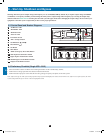
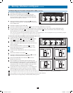
• For the first UPS system you wish to transfer to manual bypass
mode, press the OFF button
A
for 3 seconds (until you hear
a beep), then release the button. If the other UPS systems can
support the connected equipment loads, the UPS system that was
turned off will shut down its inverter and its LCD screen will read
“LOAD NOT POWERED”. All other UPS systems’ LCD screens
will read “ONLINE MODE”. If the total connected equipment load
is too large to be handled by the remaining UPS systems, all UPS
systems will shut down their inverters and switch to bypass mode,
and their LCD screens will read “ON AUTO BYPASS”. Repeat
step 1 for each UPS system you wish to transfer to manual bypass
mode.
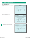
Confirm that all UPS systems are in auto bypass mode.
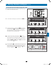
• Switch off the main input circuit breaker switch
Q1
of each UPS
system.
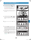
• Switch on the manual bypass input circuit breaker switch
Q3
of
each UPS system. The bypass power path will power the loads and
all LCD screens will read “ON MANUAL BYPASS”.
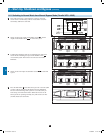
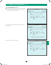
• Switch off the bypass input circuit breaker switch
Q2
and the
output circuit breaker switch
Q4
of each UPS system. Wait for the
power module fans and the LCD screen to turn off completely (this
may take a minute or two).
1
2
3
4
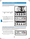
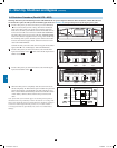
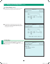
• Switch off the external battery cabinet circuit breaker switch of
each battery cabinet.
• In this mode, only the manual bypass path (including the manual
bypass circuit breaker
Q3
), the load terminals of the output
circuit breaker switch
Q4
and the terminal block
B
contain
hazardous voltage, allowing qualified service personnel to perform
maintenance or repair. Note: Qualified service personnel may
prefer to de-energize the UPS systems completely, depending
on local codes and the nature of the maintenance or repair. Use
of a parallel cabinet with system level maintenance bypass is
recommended.
5
6
12-212-93-3141.indb 27 12/28/2012 11:17:51 AM