


1
5
9
3
7
11
2
6
10
4
8
12
13
14
29
9 – Power Module Status and Replacement
Warning: Only authorized Tripp Lite service technicians with knowledge and operational training of this equipment
should install, repair or remove any system components, including power modules. Only power modules with the same
firmware versions may be placed within the same UPS system frame. Verify power module firmware version before
replacement. Permanent power module removal or addition can only be performed by Tripp Lite authorized service
technicians.
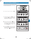
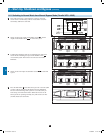
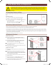
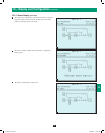
9-1 Power Module Features and Status
Each Power Module features an LED indicator to inform the user of its
status.
LED Indicator Statuses
“ON”—The power module is active and functioning properly.
“FLASHING”—The power module has failed and is offline.
“OFF”—When the locking latch is in “UNLOCKED” ( ) position, the
power module is inactive.
When the locking latch is in “LOCKED” ( ) position and the
main power is on, the power module has failed.
9-2 Preliminary Replacement Checklist
• BeforeremovingaPowerModule,ensurethattheremainingPowerModulescansupporttheconnectedload.
• VerifythatthePowerModuleneedsserviceorreplacementviaitsindividualLEDstatusindicator.
• DonotattempttoremovePowerModulesbyyourself.PowerModulesweigh30kg(66lb)andrequireatleasttwopeopleforproperhandling.
• PowerModulescanbereplacedinanyUPSOperatingMode.Itisnotnecessarytopowerloadsofforleavethemunprotected.Note: UPS must
be able to support load without the Power Modules to be replaced. If the UPS cannot handle the load once the Power Module is deactivated, an
overload will occur and the UPS will shut down.
• Replacepowermoduleswithsamefirmwareversiononly.
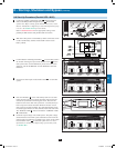
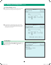
9-3 Replacement Procedure
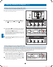
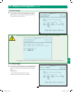
To Remove Power Module
1. Remove the bezel cover of the Power Module you wish to
replace. Verify that there is a fault through the individual LED
status and UPS LCD screen.
2. Deactivate the Power Module by turning the spring-activated
knob of the locking latch counter-clockwise until it pops out.
Move the locking latch to “UNLOCKED” ( )
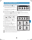
3. Use a screwdriver to remove the screws on either side of the
Power Module (total of 4).
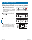
4. With one person on either side of the Power Module, pull out and
lift the module from the UPS frame.
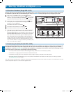
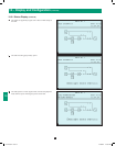
To Replace Power Module:
Verify power module replacement has the same firmware version
(as labeled).
With one person on either side of the repaired or new Power
Module, lift and align the Power Module into the appropriate slot
on the UPS. Slide the Power Module in until it is fully inside the
unit and seated flush with its brackets.
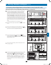
Use a screwdriver to fasten the screws on either side of the Power
Module (total of 4).
Move the locking latch to “LOCKED” ( ) position and turn
clockwise until it pops in. Power Module will activate.
9
Verify that the Power Module is activated via the status LED and
UPS LCD screen before replacing the bezel cover.
1
2
3
4
5
6
7
8
12-212-93-3141.indb 29 12/28/2012 11:17:53 AM