


50 Zebra S-Series User’s Guide
6LJQDO'HVFULSWLRQV
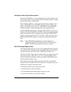
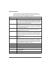
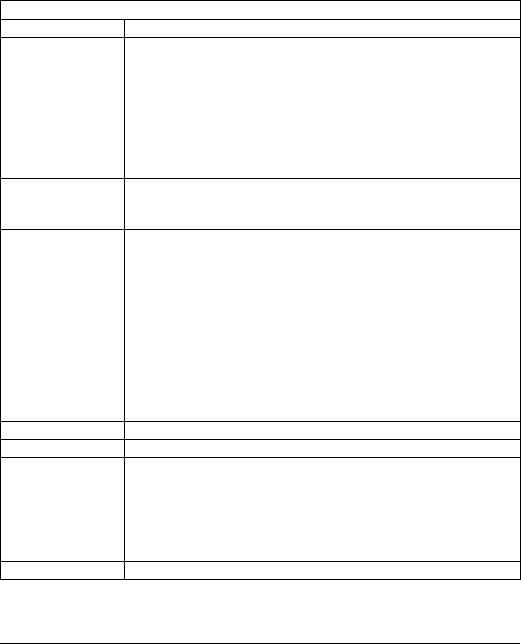
The following chart provides a description of each of the pins in the
parallel connector. A standard parallel data cable provides the required
interconnection between the computer and the printer.
Parallel Connector Pin Assignments
Pin No. Description
1 The nStrobe printer input has internal 3.3 kW pull-up resistors to 5 V
(I
OL
= 1.5 mA) and is designed to receive a signal driven open collector
V
OL
<= 0.8 V. This pin is a signal from the host computer. The nStrobe
input is debounced on a LOW going edge to require an active width
greater than 0.5 ms before data is latched.
2-9 Data inputs have TTL input characteristics with internal 3.3 kW pullups
and represent 1 TTL unit load or less. The data inputs are positive logic
with a HIGH voltage level corresponding to a logic 1. Pin 2 through Pin
9 = D0 through D7 respectively.
10 The nAck output is an active LOW pulse used to indicate termination.
nAck is a driven open collector with a 3.3 kW internal pull-up. The
output sinks 7 mA to a V
OL
<= 0.4 V.
11 The Busy output is active HIGH whenever the printer cannot accept
data due to any normal or abnormal condition, including buffer overflow,
head open, over temperature, and media error conditions. Busy is a
driven open collector with a 3.3 kW internal pull-up. The output sinks 7
mA to a V
OL
<= 0.4 V.
12 The PError signal is active HIGH whenever the printer is out of media or
ribbon.
13 The Select signal function is determined by an additional configuration
option which becomes active when the port is present. In the default
condition, select is active HIGH whenever the parallel port is powered
up and the parallel port is enabled. In the non-default condition, select
is active LOW whenever the printer is printing.
14 nAutoFd (not connected).
15 Not defined.
16 Logic Gnd.
17 FRAME GROUND is at the same potential as Logic Gnd (pin 16).
18 FUSED 5 V - 1 A maximum.
19-30 SIGNAL GROUNDS are the Logic Grounds and Returns for all input
and output signals.
31-35 NOT USED - These leads should be left unconnected.
36 NSelectIn (not connected).