


Parallel Interface
The parallel interface provides a means of communication which is typically faster than
the previously mentioned serial interface method. In this method, the bits of data which
make up a character are sent all at one time over several wires in the cable, one bit per
wire.
Data signals are defined as either HIGH or LOW while control signals are either Active
or Inactive. This distinction is due to the fact that some Control Signals are active HI
while others are active LOW. The voltage levels which represent these conditions are:
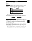
Data Signal Voltage Level
HIGH = +5 VDC
LOW = 0 VDC
Parallel Cabling Requirements
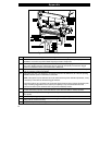
The required cable must have a standard 36-pin parallel connector on one end, which is
plugged into the mating connector located inside the access opening on the left side of the
printer. Refer to Figure 1 on page 3. The parallel interface cable would be connected using
bail clips, instead of screws, in a similar position as the serial data cable shown in the
illustration.
The other end of the parallel interface cable connects to an appropriate point at the host
computer.
Data cables must be fully shielded and fitted with metal or metallized connector shells.
Shielded cables and connectors are required to prevent radiation and reception of
electrical noise.
To minimize electrical noise pickup in the cable:
1. Keep data cables as short as possible.
2. Do not bundle the data cables tightly with power cords.
3. Do not tie the data cables to power wire conduits.
Appendix
Appendix
67