Signal Descriptions
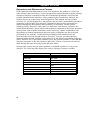
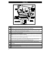
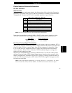
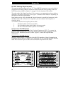
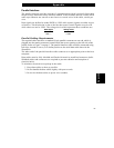
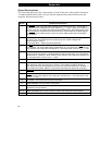
The following chart provides a description of each of the pins in the parallel connector.
A standard parallel data cable will provide the required interconnection between the
computer and the Stripe printer.
Pin No. Parallel Connector Pinout
1The STROBE printer input has internal 3.3K pull-up resistors to 5V (I
OL
= 1.5mA) and is
designed to receive a signal driven open collector V
OL
<= 0.8V. This pin is a signal from
the host computer. Its LOW going edge will latch the data at the eight DATA inputs. Data
is non-transparently latched so as to avoid hold time requirements on the DATA signals.
The
STROBE input is debounced to require an active width greater than 0.5 µS before
data is latched.
2 - 9 DATA inputs have TTL input characteristics with internal 3.3K pullups and represent 1 TTL
unit load or less. The DATA inputs are positive logic with a HIGH voltage level
corresponding to a logic 1.
Pin 2 through Pin 9 = D0 through D7 respectively.
10 The
ACK output is a 12 microsecond active LOW pulse indicating that the printer is ready
to accept data. The active LOW state precedes BUSY by 7 microseconds.
ACK is driven
open collector with a 3.3K ohm internal pull-up. The output sinks 7 mA to a V
OL
<= 0.4V.
11 The BUSY output is active HIGH whenever the printer cannot accept data due to any
normal or abnormal condition, including Buffer Overflow, Head Open, Over Temperature,
and Media Error conditions. BUSY is driven open collector with a 3.3K ohm internal pull-
up. The output sinks 7 mA to a V
OL
<= 0.4V.
12 The PAPER OUT signal is active HIGH whenever the printer is out of media or ribbon.
13 The SELECT OUT signal function is determined by an additional configuration option
which becomes active when the port is present. In the default condition, SELECT is
active HIGH whenever the parallel port is powered up and the parallel port is enabled. In
the non-default condition, SELECT will go active LOW whenever the printer is printing.
14 AUTOFEED is unterminated in the printer.
15 The
ERROR output (Pin 15) is active LOW whenever any error condition is present.
ERROR is driven open collector with a 3.3K ohm internal pull-up. The output sinks 7 mA
to a V
OL
<= 0.4V.
16 NOT USED - This lead should be left unconnected.
17 FRAME GROUND is unterminated in the printer.
18 UNDEFINED in this Parallel Interface. (In other interfaces, pin 18 may supply 50 mA at
+5V which is fuse protected.)
19 - 30 SIGNAL GROUNDS are the Logic Grounds and Returns for all input and output signals.
31 - 36 NOT USED - These leads should be left unconnected.
Appendix
68


