


Zebra Z4M/Z6M Printers User’s Guide 87
®®lcà
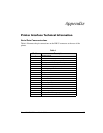
3ULQWHU,QWHUIDFH7HFKQLFDO,QIRUPDWLRQ
6HULDO'DWD&RPPXQLFDWLRQV
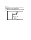
Table 6 illustrates the pin connections on the DB-25 connector at the rear of the
printer.
Table 6
Pin No. Description
1 Chassis ground
2 TXD (transmit data) output from the printer
3 RXD (receive data) input to the printer
4 RTS (request to send) output from the printer
5 Not used
6 DSR (data set ready) input to the printer
7 RS-232 signal ground
8 Not used
9 +5v @ 1A source
10 Not used
11 RS-485 signal ground
12 Not used
13 RS-485 input A(-)
14 RS-485 output A(-)
15 Not used
16 RS-485 input B(+)
17 and 18 Not used
19 RS-485 output B(+)
20 DTR (data terminal ready) output from the printer
21-25 Not used