EES-1024AF Intelligent Ethernet Switch
Hardware Connections 2-3
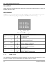
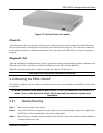
Figure 2-3 The Rear Panel of the switch
Power On
After all network cables are connected, plug the power cord into the power socket on the back panel and the other
end into a power outlet. Turn the power on using the power Switch on the back panel. The switch uses a universal
power supply that requires no additional adjustment. Check the front panel PWR LED to see if power is properly
supplied.
Diagnostic Test
After the installation is completed and AC power is applied, the switch will automatically perform a diagnostic test.
When the Power LED is on within 5 seconds, the Diagnostic status LEDs will soon flash red.
When the switch passes the self-test within 15 seconds, the Link /ACT LED turns on.
If the switch fails the self-test, the ALM LED will blink.
2.2 Mounting the EES-1024AF
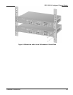
The switch is suitable for use in an office environment where it can be rack-mounted in standard EIA 19-inch racks
or standalone.
For proper ventilation, allow about at least 4 inches ( 10 cm ) of clearance on the front and 3.4
inches ( 8 cm ) on the back of the switch. This is especially important for enclosed rack
installation.
2.2.1 Desktop Mounting
Step 1. Make sure the switch is clean and dry.
Step 2. Set the EES-1024AF on a smooth, level and sturdy flat space strong enough to support the weight of the
EES-1024AF and the attached cables with a power outlet nearby.
Step 3. Make sure there is enough clearance around the EES-1024AF to allow air circulation and the attachment
of cables and the power cord.


