


Bridging and Routing Models 3-7
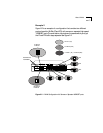
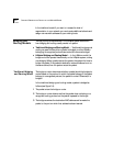
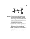
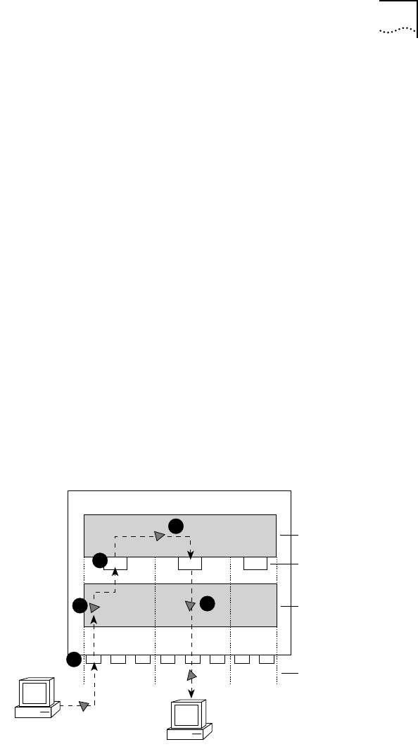
In the LANplex bridging and routing model, a packet is routed as follows
(see Figure 3-7):
1 The packet enters the LANplex system.
2 The packet’s destination address is examined by the bridging layer.
3 The destination address corresponds to the address of one of the system
ports configured for routing (as opposed to a learned end-station address).
The packet is passed to the router interface associated with the port on
which the packet was received.
4 The routing layer:
a Selects a destination interface based on the destination network
address.
b Determines the MAC address of the next hop (either the destination
host or another gateway).
c Passes the packet back to the bridging layer.
5 The bridging layer then selects a segment (port) based on the destination
MAC address and forwards the packet to that segment.
Figure 3-7 Routing in the LANplex Bridging and Routing Model
1
Transmitting Host
3
Destination Host
5
2
1
2
3
Router Interfaces
Bridging Layer
Routing Layer
Subnets
4
123
Router
Bridge