


Installing the ISDN LAN Modem 27
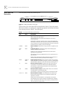
Back Panel Connector
Description
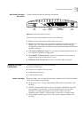
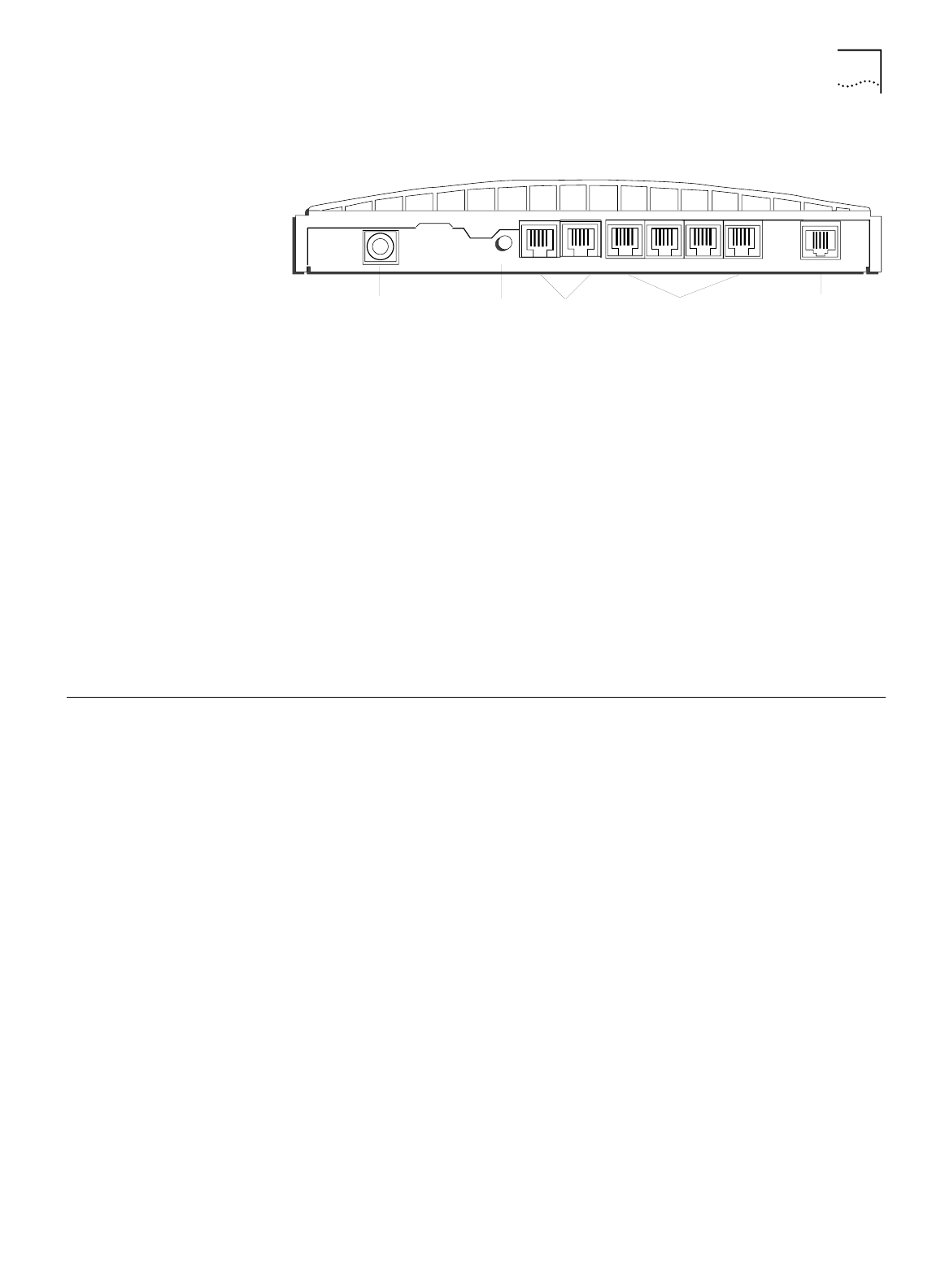
The back panel provides the following components.
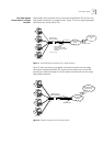
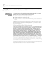
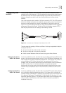
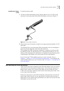
Figure 12
ISDN LAN Modem Back Panel
From left to right the back panel consists of the following.
■
Power: Connect the power module cable to this port.
■
Reset: Press this button for no more than a couple of seconds if you have to
reset the unit. This causes the software to restart while maintaining your
configuration profile which includes service provider information and ISDN line
telephone numbers.
■
Two Analog Telephone Ports: You can connect analog equipment such as a
fax machine or telephone to these ports.
■
Four 10BASE-T Ethernet Ports: Connect the computers to these ports or
another Ethernet hub to add up to 25 users.
■
ISDN Basic Rate Interface Port: Connect the ISDN cable to this port.
Installing the ISDN
LAN Modem
This section describes how to do the following.
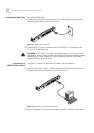
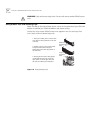
■ Install the ISDN cable
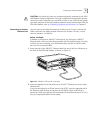
■ Connect to a 10BASE-T Ethernet LAN
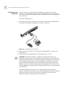
■ Install analog equipment
■ Install the power cable
Before You Begin
Before you begin, you will need the following in addition to the ISDN LAN Modem
which was provided in the package:
■ RJ-45 (8-pin) to RJ-11 (6-pin) cable labeled ISDN which was provided in the
package.
■ 10BASE-T Ethernet cable (8-pin to 8-pin connectors) labeled Ethernet which
was provided in the package. It is recommended that you use the cable
provided. If, however, you choose to use another cable it must be a
straight-through 10BASE-T Ethernet cable. It cannot be a crossover cable.
■ Power adapter provided (you must use the power adapter provided in the
package).
RESET
10-18 VDC
0.8 A MAX
ISDN
1 PHONE 2
LAN
Power
Connector
Reset Button
Two Analog
Telephone Ports
Four Ethernet
10Base-T Connectors
ISDN
BRI Interface
4
3
1
2