


103
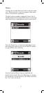
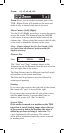
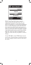
TDR Save
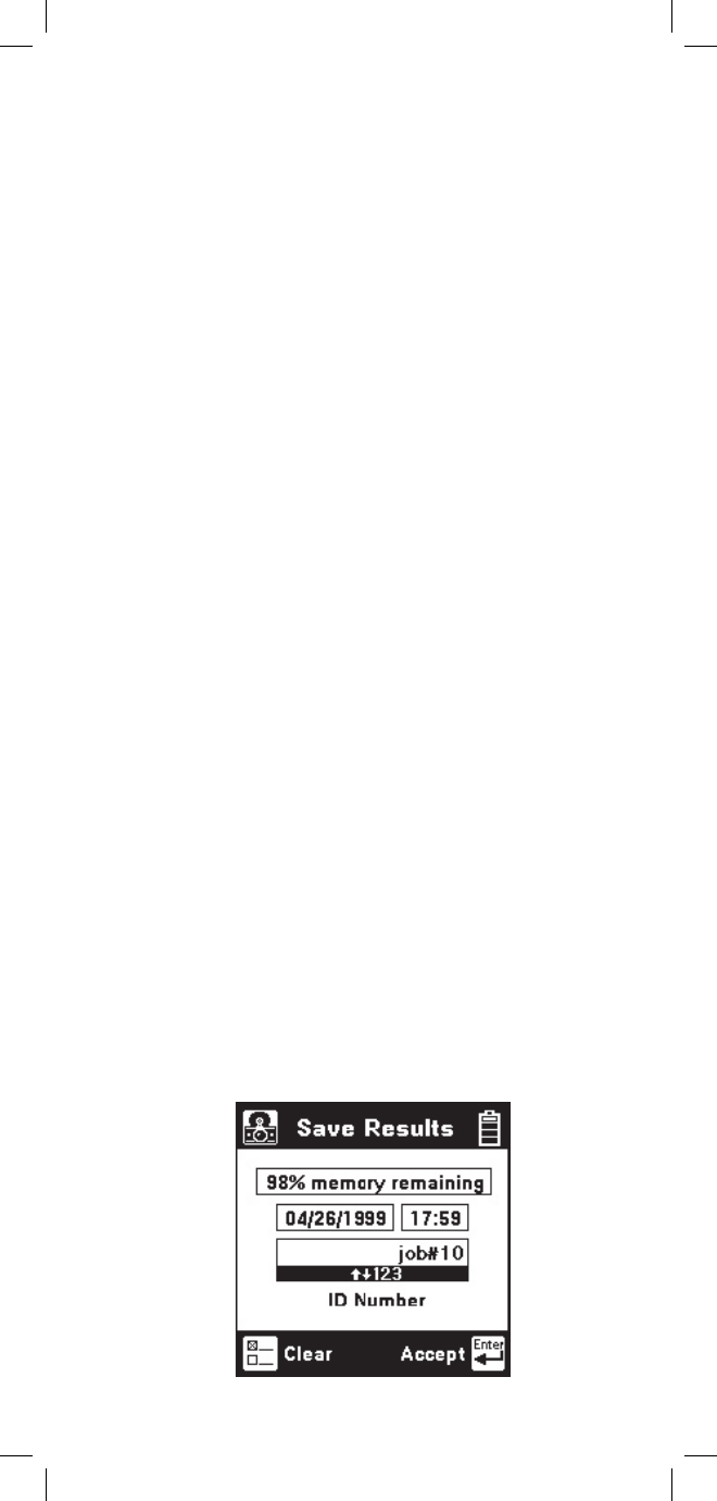
You can save only the active “Single Trace” TDR
screen. First, select the TDR control parameters so the
screen appears as desired. Press the [Save] key (camera
icon). The 965DSP will display the Save Results screen
as follows:
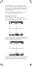
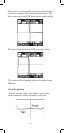
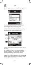
‘Peak’ Events
Launch Pulse: The first peak on the screen is the
“launch pulse” which occurs where the 965DSP connects
to the test leads (at a distance of 0 feet or meters). The
distance to the cursor includes the five foot length of the
test leads.
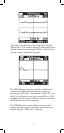
Open: A clean or partial open will show up as a peak
on the screen. The “cleaner” the open, the taller the peak.
A complete open will be the tallest peak (other than the
launch pulse). You can not see events past a complete
open.
Load Coil: A load coil looks very similar to an open. If
you think there is a load coil on the pair, use the 965DSP
Load Coil function (in the Toolbox) to verify its presence.
You can not see events past a load coil.
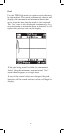
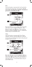
‘Dip’ Events
Fault: A resistance fault will show as a dip on screen.
The lower the value of resistance, the lower the dip.
Short: A short (or zero-Ohm resistance fault) will show
up as the lowest dip on the screen. You cannot see events
past a short.
Bridge Tap: A bridge tap will look like a resistance fault
and an open. (A dip followed by a peak.) The distance
between the two events is the length of the bridge tap.
The start of a bridge tap looks like a resistance fault. Use
the 965DSP Resistance function to measure the resistance
on the pair. If there is no resistance, and you see a dip
followed by a peak, you might suspect a bridge tap.