


59
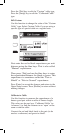
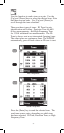
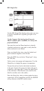
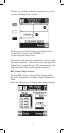
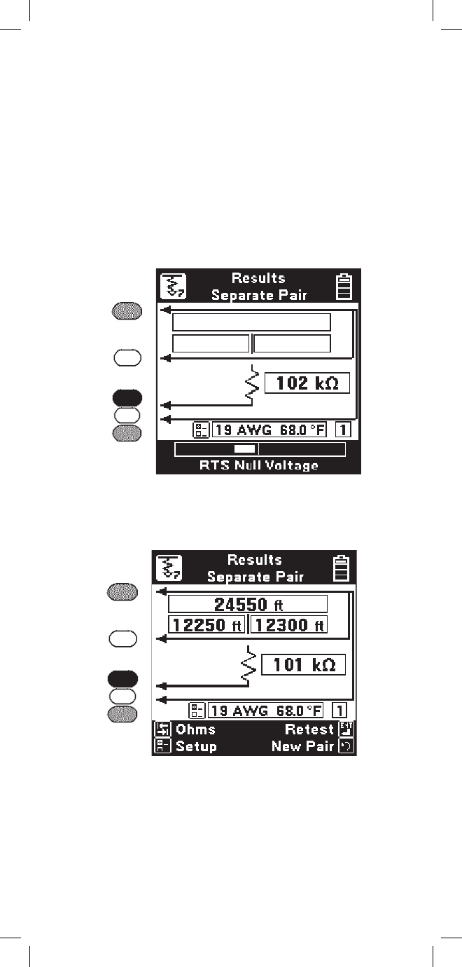
During the measurement a bar graph of the
measurement null voltage for RTS and then RTF will
be visible at the bottom of the screen.
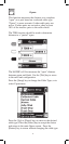
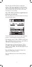
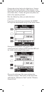
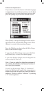
Connect the red test lead to the faulted wire. Connect
the black Lead to the reference. (The reference is the
return path for the fault and can be the shield or another
wire in the cable.) Connect the green and yellow test
leads to the separate good pair.
Press the [Enter] key after you make the above
connections.
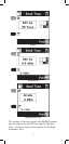
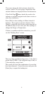
If no errors in the hook-up are detected, the 965DSP
will begin the measurement and go to the results screen.
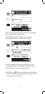
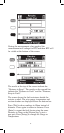
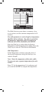
The results at the top of the screen indicate the
“Distance to Strap”. The results on the second line
indicated the “Distance to Fault” and the “Distance,
Strap to Fault”.