


Instrument Logical
Addresses
Instruments are identified by a logical address which directly relates to its GPIB
secondary address. Instruments come from the factory with a preset logical
address. You can change the factory setting during installation (see the "Agilent
75000 Series B Installation and Getting Started Guide" for instructions).
A single-module instrument must have its logical address set to an integer
multiple of 8 (0, 8, 16, 24, ... 240). In a multiple-module instrument, only one of
the modules has a logical address that is an integer multiple of 8. The other
modules in the multiple-module instrument must have consecutive logical
addresses. For example, in a Scanning Voltmeter, if the voltmeter module has a
logical address of 16, the other modules in that instrument must have logical
addresses of 17, 18, 19 and so on. The same applies to the System Instrument
who’s logical address fixed at 0. An E1324A plug-in serial interface controlled
by the System Instrument would be set to logical address 1. A second E1324A
would be set to logical address 2 and so on.
Instrument Secondary
Addresses
An instrument’s GPIB secondary address is simply the logical address divided
by 8 (for a multiple-module instrument, the lowest logical address divided by 8).
For example, an instrument with a logical address of 16 has a secondary address
of 02. The secondary address allows access to a particular instrument when
programming via GPIB. (The System Instrument’s secondary address is 00 and
is the only address that cannot be changed).
Unassigned Modules An unassigned module in an E1300B/E1301B Mainframe is one that does not
have a logical address that is a multiple of 8 (8, 16, 24...240) and is not part of a
Scanning Voltmeter or Switchbox configuration. You can only program these
modules at the register level using the VXI:WRITE and VXI:READ?
commands (see Chapter 5 of this manual for more information on these
commands).
1
Introductory
Programming
Examples
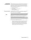
This section shows how to send SCPI and Common Commands to the
mainframe’s System Instrument and how to read data back. The following
assumes that you send the commands or read the data over GPIB. To send SCPI
commands or to read data, specify the:
• Computer’s GPIB interface address
• Mainframe’s GPIB primary address
• Instrument’s GPIB secondary address
• SCPI command string or Common Command
For instruments in the mainframe, the primary address is the same as the
mainframe address (i.e., the factory setting is 09). The instrument’s secondary
address is simply the logical address divided by 8 (e.g., logical addresses of 8, 16,
24, or 32, result in secondary addresses of 01, 02, 03, or 04, respectively).
1-4 Getting Started