


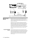


Example: Synchronizing an Internal Instrument to an External Instrument
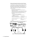
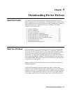
This example uses the mainframe’s Trig Out and Event In ports to synchronize
an external multimeter to a multiplexer installed in the mainframe. Connections
are shown in Figure 4-3. The multimeter’s Voltmeter Complete port outputs a
pulse whenever the multimeter has finished a reading. The multimeter’s
External Trigger port allows the multimeter to be triggered by a negative going
TTL pulse. Since the synchronization is independent of the GPIB bus and the
computer, readings must be stored in the multimeter’s reading memory. The
sequence of operation is:
1. INIT (line 50) closes channel number 100.
2. The channel closure causes a pulse on Trig Out which triggers the
multimeter to take a reading.
3. When the reading is complete it is stored in multimeter memory and the
multimeter outputs a pulse on its Voltmeter Complete port. This signals
the multiplexer to advance to the next channel in the scan list.
4. Steps 2 and 3 are repeated until all channels have been scanned and
readings taken.
10 OUTPUT 722;"TRIG EXT;DCV;MEM FIFO"
Set multimeter to external trigger, DC volts, enable reading
memory
20 OUTPUT 70914;"OUTP ON" Enable Trig Out port
30 OUTPUT 70914;"TRIG:SOUR EXT" Set multiplexer to advance scan
on external signal
40 OUTPUT 70914;"SCAN (@100:115)" Specify scan list (channels 100
to 115)
50 OUTPUT 70914;"INIT" Close first channel (starts
scanning cycle)
60 END
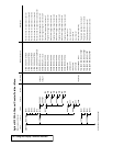
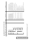
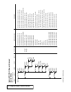
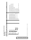
Example: Synchronizing Internal/External Instruments and the Computer This
example uses the mainframe’s Trig Out port to synchronize an external
Figure 4-3. Synchronizing Internal/External Instruments
4-4 Using the Mainframe