


Chapter 4
Using the Mainframe
Using this Chapter This chapter shows how to use the mainframe’s Pacer function, how to change
the primary GPIB address, and how to synchronize internal and external
instruments using the mainframe’s Event In and Trigger Out ports. This chapter
also discusses how mainframe memory is used by installed instruments. Where
possible, examples show only the command string sent to the instrument (no
information about a computer language or interface is shown). Examples that
require showing a computer language are written for HP 9000 Series 200/300
Computers using BASIC language and the GPIB interface. This chapter
contains the following sections:
• Using the Pacer. . . . . . . . . . . . . . . . . . . . . . . . . . . . . . . . . . . . . . . . 4-1
• Changing the Primary GPIB Address . . . . . . . . . . . . . . . . . . . . . 4-3
• Synchronizing Internal and External Instruments . . . . . . . . . . . 4-3
• Mainframe Data Memory . . . . . . . . . . . . . . . . . . . . . . . . . . . . . . . 4-6
1
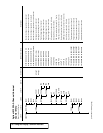
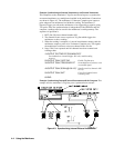
Using the Pacer The Pacer generates a square wave signal on the mainframe’s rear panel Pacer
Out connecter. The signal levels are standard TTL levels (0V to 5V). The Pacer
signal can be used to trigger or pace external equipment such as scanners or
voltmeters. Figure 4-1 shows a single cycle of the Pacer output with a specified
period of 1 second.
The following SCPI commands control the Pacer:
Figure 4-1. Pacer Out Square Wave
Using the Mainframe 4-1