


7 -6 Agilent Technologies Z5623A Option H48
Advanced Topics
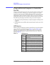
Using the Control Lines Connector
Using the Control Lines Connector
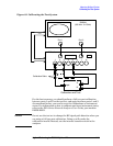
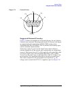
The Control Lines connector allows the test set to control other
equipment. See Figure 7-1, “Control Lines,” on page 7-7 for a diagram of
the connector. The diagram identifies the ground pin and the pin that is
associated with each of the five control lines (C1 through C5). (Notice
that the connector has three unused pins.)
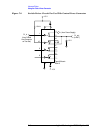
The connector is driven by open-collector output drivers within the test
set. The drivers cannot source any current. Therefore, the user must
provide an external power supply and some additional circuitry in order
to use the connector. The next paragraph describes the absolute
maximum limits associated with the connector. The remainder of the
section describes possible ways of implementing the additional circuitry
needed in order to use the connector.
Each control line on the test set can be independently set to either the
“Open” state or the “Low” state. In the “Open” state, the voltage on the
line will be set by the external power supply. This voltage must not
exceed +22 Vdc. In the “Low” state, the voltage on the line will be about
+0.63 Vdc. In the “Low” state, the drive circuitry can sink a maximum
of 250 mA per control line.
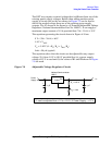
Control Line Commands for 9-Pin Connector:
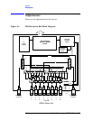
Figure 7-1 on page 7-7
presents a diagram of the 9-pin connector and
identifies the control lines (C1 through C5). To set the control lines,
send the test set a number (either binary or decimal) specifying the
state of all five lines. The binary number has the following format:
0 0 0 C5 C4 C3 C2 C1
Note that three leading zeroes are required. Note, also, that a 1 for a
given control line specifies a low (+0.63 V) and a 0 specifies an open. For
example, if the test set has an address of 12, the following command
will set C3 and C1 low, and C5, C4, and C2 high:
OUTPUT 712;"00000101;" ! sets C5-C1 to OOLOL
The decimal equivalent of the binary number can also be used:
OUTPUT 712;"5;" ! sets C5-C1 to OOLOL
Table 3-3 on page 3-10 lists all possible combinations of control line
states. For each combination, the table lists the binary and decimal
numbers required to command that combination.