


Agilent Technologies Z5623A Option H48 8 -5
Service
Troubleshooting
Troubleshooting
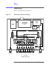
This section contains procedures for troubleshooting the test set to
assembly level only. These procedures should enable you to determine
whether the power supply, front panel, or main switch board needs
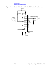
replacing. Refer to the system block diagram (Figure 8-1 on page 8-2) as
an aid in troubleshooting.
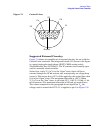
General Troubleshooting Notes
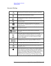
WARNING
Always turn the instrument power off before removing or
installing an assembly.
WARNING
Some parts in the instrument have sharp edges. Work carefully
to avoid injury.
CAUTION
If you need to disassemble the instrument, be sure to work at an
antistatic workstation and use a grounded wrist strap. This will protect
the instrument from electrostatic discharges (ESD) that could damage
the instrument.
CAUTION
After identifying a defective assembly or board, inspect it for obvious,
easy-to-fix defects such as bent pins on ICs or cold solder joints. Repair
of these defects by qualified personnel will restore the instrument to
normal operation much more rapidly than ordering a replacement
assembly or board.
Troubleshooting Power Supply Problems
Turn the instrument on. Check the condition of the LCD on the front
panel:
• If it is off, there is still a possibility that the power supply is not
supplying the necessary +24V, +12V, and +5V to the main board.
• If the LCD is off, check the main fuse located in the power supply
filter at the rear of the instrument.
• If the LCD is still off, check the cable between the main board and
front panel board.
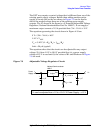
• Finally, disconnect the DC power cable from the power supply to the
main switch board and measure the voltages. They should be +15V,
+12V, and +5V. If not, replace the power supply.