


2 -10 Agilent Technologies Z5623A Option H48
Installation
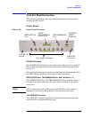
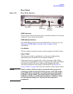
Test Set Familiarization
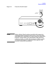
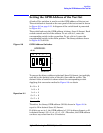
The PORT CONNECTION Status LCD
The PORT CONNECTION Status LCD displays the following:
• Which test port is connected to the REFLECTION port
• Which test port is connected to the TRANSMISSION port
• The status (O = “Open”, L = “Low”) of each of the five control lines
(C5 through C1)
All test ports not displayed on the Status LCD are internally
terminated in 50 Ω.
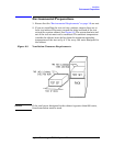
The CONTROL LINES Connector
The 9-pin CONTROL LINES Connector provides the user with a way of
controlling either the Device Under Test (DUT) or other equipment. The
test set cannot source any current from this connector. Therefore, the
user must provide an external power supply and some additional
circuitry if he wishes to use the connector. Refer to“Using the Control
Lines Connector” on page 7-6 for further details.
CAUTION
Do not apply more than +22 Vdc to pins 1 through 5 of the CONTROL
LINES Connector.
CAUTION
Do not employ external circuitry that forces the test set to sink more
than 250 mA on any control line (pins 1 through 5 of the CONTROL
LINES Connector) when that line is commanded to the “Low” state
(+0.63 Vdc).