


Agilent Technologies Z5623A Option H48 2 -13
Installation
Setting the GPIB Address of the Test Set
Setting the GPIB Address of the Test Set
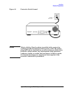
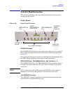
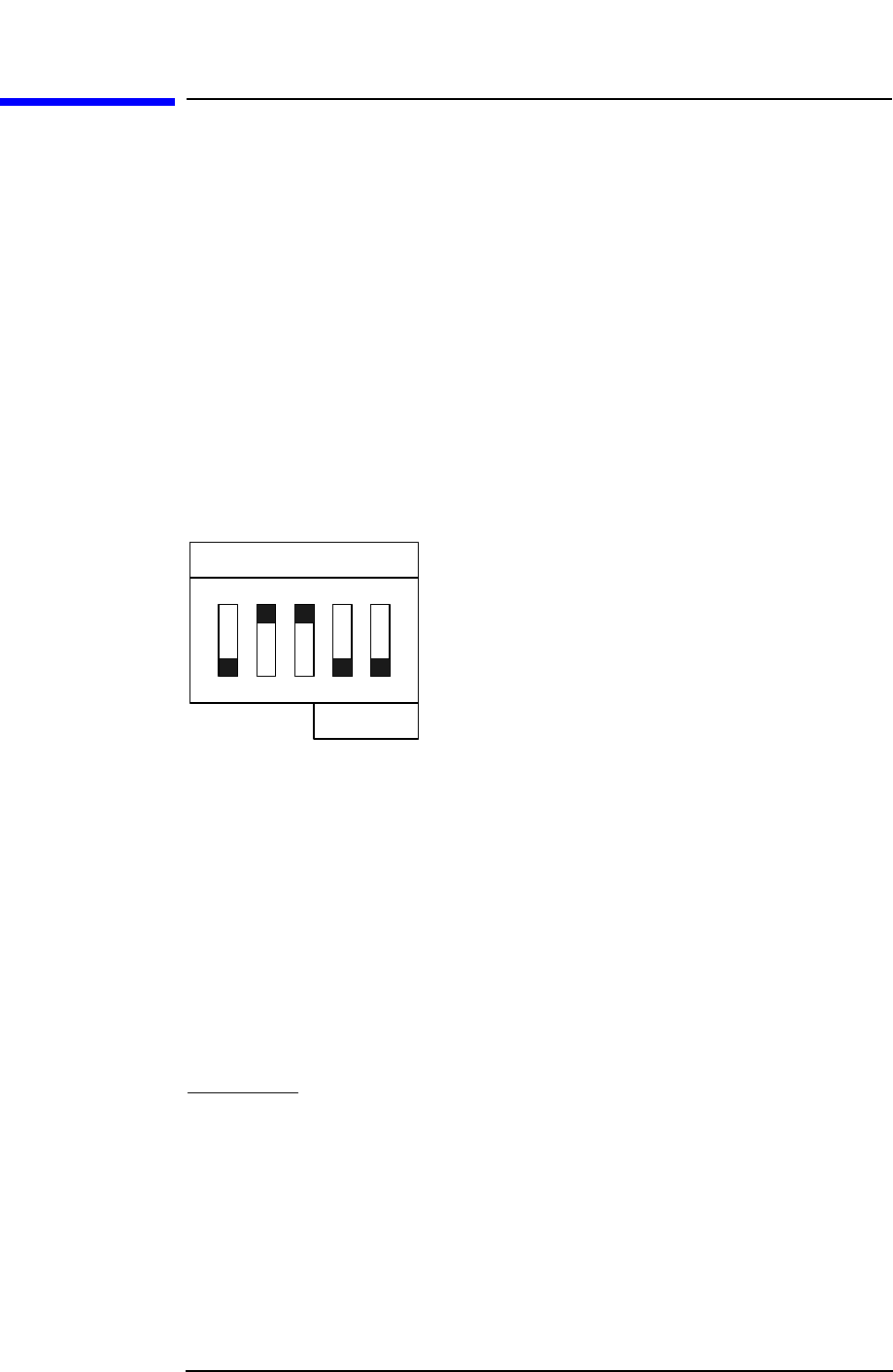
A bank of five switches is used to set the GPIB address of the test set.
The switch bank is located on the rear panel of the test set and is shown
in Figure 2-6 on page 2-11. A diagram of the switch bank is presented
in Figure 2-8.
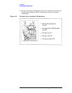
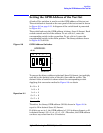
The switch bank sets the GPIB address in binary (base 2) format. Each
switch controls one bit of the address. To set a bit to 1, move the
corresponding switch to the up position. To set a bit to 0, move the
corresponding switch to the down position. The binary address shown
in Figure 2-8 is 01100.
Figure 2-8 GPIB Address Switches
To convert the binary address to decimal (base 10) format, just multiply
each bit by the decimal value of that bit, then add the results. The
decimal value of each bit is shown above the corresponding switch.
Applying this conversion method to Figure 2-8 we obtain
Equation 2-1
Therefore, the binary GPIB address (01100) shown in Figure 2-8 is
equal to 12 in decimal (base 10) format.
If all bits are set to 1, the GPIB address is 11111 in binary format, or 31
in decimal format. (16 + 8 + 4 + 2 + 1 = 31.) Therefore, the GPIB address
can have any value from 0 to 31 inclusive.
HP-IB
PARALLEL
ADDRESS:
168421
12
1
0
016× 0=
18× 8=
14× 4=
02× 0=
02× 0=
Sum 12=