


Agilent Technologies Z5623A Option H48 7 -7
Advanced Topics
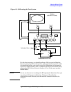
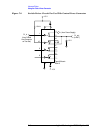
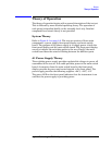
Using the Control Lines Connector
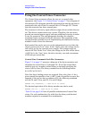
Figure 7-1 Control Lines
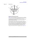
Suggested External Circuitry
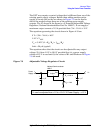
Figure 7-2 shows one possible set of external circuitry for use with the
Control Lines connector. The integrated circuit (IC) shown in the figure
is a quad single-pole-single-throw (SPST) CMOS analog switch
(Temic/Siliconix Part No. DG413). The IC contains two normally open
and two normally closed switches.
Notice that, when “C1_in” is in the “Open” state, there will be no
current through the 10 kΩ resistor and, consequently, no voltage drop
across it. This means that +15 V will be applied to the control line when
it is in the “Open” state. (The maximum allowable is +22 V.) When
“C1_in” is in the “Low” state, it will sink (15 V - 0.63 V) / 10 kΩ = 1.44
mA of current. (The maximum allowable is 250 mA per control line.)
The values computed in this paragraph do not depend on V
C
, the
voltage used to control the DUT. (V
C
is applied to pin 3 in Figure 7-2.)
15
96
C1
C2
C3
C4
C5
Ground