


Agilent Technologies Z5623A Option H48 2 -9
Installation
Test Set Familiarization
Test Set Familiarization
This section familiarizes the user with various front and rear panel
features of the test set.
Front Panel
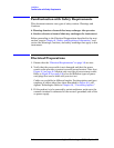
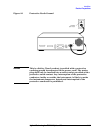
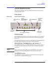
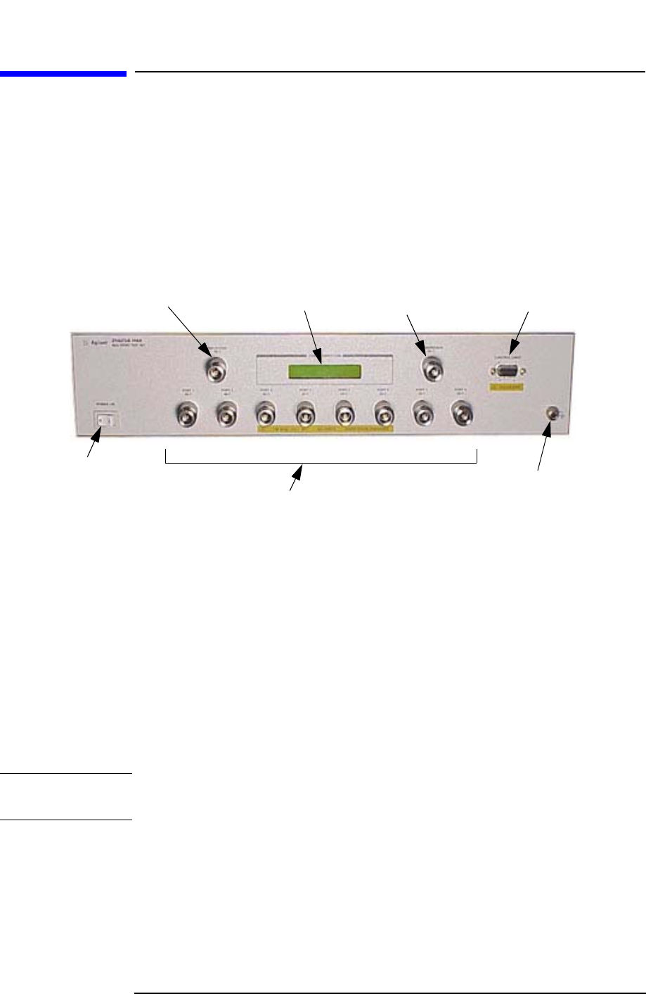
Figure 2-5 Front Panel Features
POWER ON Switch
The POWER ON Switch turns the AC power to the test set on and off.
The switch is located at the bottom left corner of the front panel. See
Figure 2-5.
The switch disconnects the mains circuits from the mains supply after
the EMC filters and before other parts of the instrument.
REFLECTION Port, TRANSMISSION Port, and Test Ports 1–8
The REFLECTION Port, the TRANSMISSION Port, and Test Ports 1
through 8 are 50 Ω connectors that are used to connect to the device
under test.
CAUTION
Do not input more than 1 Watt maximum RF+DC to these ports or
damage to the internal RF switches or the analyzer may occur.
The GROUND Connector
The GROUND Connector provides a convenient front panel ground
connection for a standard banana plug.
REFLECTION
Port
PORT
CONNECTION
Status LCD
TRANSMISSION
Port
CONTROL
LINES
Connector
POWER ON
Switch
Test Ports 1 through 8
GROUND
Connector