


Application Example 1
Page 24-3
Omni Switch/Router
12345678
123456
VLAN A
Internal
IP
Router
1
2
5
.0
.0
.3
5
1
3
0
.0
.0
.2
2
IP Nnetwork 125.0.0.0
VLAN B
IP Network 130.0.0.0
Group 2
Ports 1, 2, 3, and 4
IP Workstations
IP Workstations
125.0.0.1 125.0.0.2 125.0.0.3
125.0.0.33 125.0.0.34
IP Workstation
130.0.0.10
130.0.0.11
130.0.0.12
IP Workstation
Port 1 Port 2 Port 3 Port 4
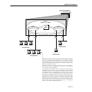
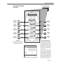
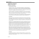
Workstation 130.0.0.11 has been moved from the segment connect-
ed to port 4 to the segment connected to port 2. When workstation
130.0.0.11 transmits its first frame from its new location, the switch
automatically places it into its original VLAN, VLAN B, because VLAN
B has a network address rule that places all devices with network
address 130.0.0.0 into VLAN B.
Both
VLAN A and VLAN B are now active on port 2. In addition,
VLAN B is now active on multiple ports – ports 2, 3, and 4. Howev-
er, this does not cause confusion.
As an example, if workstation 125.0.0.1 (in
VLAN A) wants to talk to
workstation 130.0.0.11 (in VLAN B), workstation 125.0.0.1 ARPs for
workstation 130.0.0.11’s MAC address. The address returned is that
of workstation 125.0.0.1’s default gateway, which is VLAN A’s inter-
nal IP router, 125.0.0.35. Workstation 125.0.0.1 transmits its frame to
this address and the internal IP router routes the frame to VLAN B.
When
VLAN B’s internal IP router receives the frame addressed to
workstation 130.0.0.11, it ARPs for workstation 130.0.0.11’s MAC
address if it does not already know it. The switch’s filtering data-
base identifies the port through which this MAC address can be
reached. The frame sent by workstation 125.0.0.1 to workstation
130.0.0.11 is correctly transmitted to port 2.