


Bridging Services
Page 29-14
Bridging Services
All Frame Relay Virtual Circuits (VCs) belong to a service, whether it be a Bridge, Router, or
Trunk service. By default, a virtual circuit belongs to a bridge service. No configuration is
necessary for a VC to support bridging on Group 1. However, configuration is necessary for a
VC to support Frame Relay Routing, Trunking, or Bridging on a Group other than Group 1.
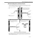
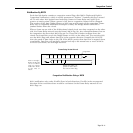
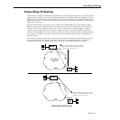
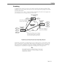
For bridging there is a one-to-one map between Frame Relay virtual circuits and switch virtual
ports. When data is received from a virtual circuit at the physical port level it automatically
maps to the corresponding virtual port. For example, if Frame Relay virtual circuit 16 maps to
virtual port 8, then all incoming data on this circuit would be incoming data on switch virtual
port 8. And if virtual circuit 17 maps to virtual port 9, then all incoming data would be on
virtual port 9.
One-to-One Mapping Between Virtual Ports and Virtual Circuits
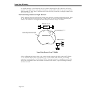
Frame Relay bridging uses standard Spanning Tree as defined in 802.1d. Typically, one bridge
port within the WAN will act as the designated root bridge (and may be the actual root
bridge) and maintain a single path through the Frame Relay network. To avoid duplication
and loops, some paths will not be allowed.
As far as Spanning Tree is concerned, the virtual ports that map off a Frame Relay physical
port are LAN ports. Each port will come up as default bridging on VLAN 1.
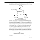
A unique aspect of Frame Relay bridging is that
MAC addresses must be learned for each DLCI
and for each virtual port. So, although the virtual circuits map directly to virtual ports, the
bridge must still learn their MAC addresses separately. Also, Frame Relay BPDUs do not have
MAC addresses.
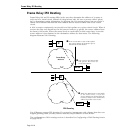
One of the disadvantages of bridging in Frame Relay is that broadcasts must be sent across all
virtual circuits that are associated with a given physical port for a given group. This require-
ment can create duplication across the Frame Relay network. At the extreme, on a full T1 line
with 96 virtual circuits defined, 96 copies of each broadcast would have to be sent for the
same Group. When using access rates at the higher end of the Frame Relay spectrum, you
could separate virtual circuits into separate Groups to decrease the size of each broadcast
domain. Or, you could use a Routing (
IP or IPX) or Trunking configuration to more efficiently
manage the data flow.
The configuration of bridging services is described in Configuring a Bridging Service on page
29-57.
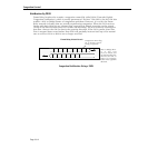
Data on VC 16
WSX
Physical
Port
Virtual
Port 8
Virtual
Port 9
Data on VC 17
Omni Switch/Router