


Chapter 8: Powering On the Stack
102
Powering On the Switches Individually
This procedure explains how you can control the assignment of the ID
numbers of the switches by powering on the units one at a time during the
initial power-on sequence. The first switch is assigned ID number 1, the
next unit is assigned ID number 2, and so on. This procedure is useful
when the switches are installed in the same equipment rack and you want
to number them in sequence, such as from top to bottom, to make them
easy to identify. After the ID number are assigned, the switches retain their
assignments even when you power off or reset the stack.
During the initial power on sequence, the first switch to be powered on
becomes the master switch of the stack. However, if you do not change
the priority values of the units, the next time you reset or power cycle the
stack the units use their MAC addresses to select the master switch. This
might result in a different switch being assigned that role. However, this
does not affect their ID number assignments, the configuration of the
switches, or the manner in which you manage the stack.
This procedure assumes the following:
This is the initial power-on sequence of the stack.
You verified that VCStack is enabled on the switches, as explained
in Chapter 6, “Verifying the Status of VCStack and Activating
VCStack” on page 85.
You connected the switches with stacking transceivers, as
explained in Chapter 7, “Cabling the Stacking Ports” on page 91.
The ID numbers are set to the default 1.
All the switches are powered off.
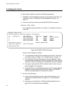
If you want to monitor the power on sequence, you may connect a terminal
or PC with a terminal emulator program to the Console port on the switch
you intend to power on first. The messages are found in “Monitoring the
Initialization Processes” on page 74.
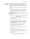
To power on the switches, perform the following procedure:
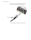
1. Power on the switch you want to have ID number 1.
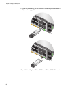
Connect the power cords to the connectors on the power supply
modules and to the appropriate power sources, as shown in
“Connecting AC Power to a Power Supply Module” on page 67 or
“Power Wiring to a DC AT-PWR250R-80 Power Supply Module” on
page 69.