


x510 Series Installation Guide for Virtual Chassis Stacking
55
Unpacking the Switch
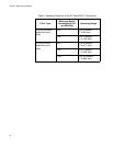
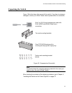
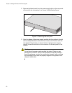
Figure 18 lists the items that come with the switch. If any item is missing or
damaged, contact your Allied Telesis sales representative for assistance.
Figure 18. Components of the switch
Note
You should retain the original packaging material in the event you
need to return the unit to Allied Telesis.
After checking the contents of the shipping containers, go to Chapter 4,
“Installing the Switch and its Power Supplies” on page 57
1947
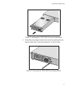
Two rack mounting brackets
One 2 m (6.6 ft) local management cable with
RJ-45 (8P8C) and DB-9 (D-sub 9-pin)
connectors.
2047
Twelve rack mounting bracket
screws
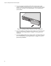
AT-PNL250
One AT-PLN250 blank panel for
covering an empty power supply bay