


Chapter 4: Installing the Switch and its Power Supplies
72
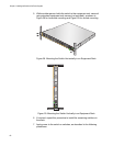
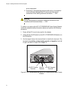
6. Connect the +48 VDC (RTN) feed wire to the terminal block marked
+(plus).
7. Connect the -48 VDC feed wire to the terminal block marked - (minus).
Warning
Check to see if there are any exposed copper strands coming from
the installed wires. When this installation is done correctly there
should be no exposed copper wire strands extending from the
terminal block. Any exposed wiring can conduct harmful levels of
electricity to persons touching the wires. E12
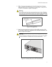
8. Secure the tray cable near the rack framework using multiple cable
ties to minimize the chance of the connections being disturbed by
casual contact with the wiring. Use at least four cable ties, separated
100mm (4 in.) apart. Locate the first one within 150mm (6 in.) of the
terminal block.
Note
This system will work with a positive grounded or negative grounded
DC system. E13
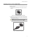
9. Verify that the circuit breaker is in the Off position.
10. Connect the supply-cable wires to the circuit breaker.
11. Energize the circuit breaker.
12. Turn the power supply module’s On/Off switch to On.
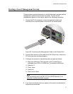
13. Start a local management session on the unit by performing the
procedure “Starting a Local Management Session,” next.
Warning
This unit might have more than one power source. To reduce the
risk of electric shock, disconnect all power cords before servicing the
unit. E30