


x510DP-52GTX Installation Guide
61
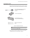
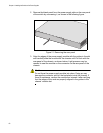
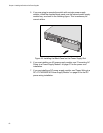
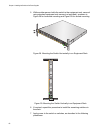
Figure 22. Installing the AT-PWR100R AC Power Supply Module
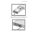
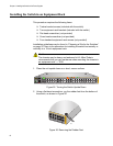
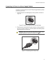
4. Secure the power supply module to the chassis by tightening the two
captive screws with a cross-head screwdriver, as shown below.
Figure 23. Securing the AT-PWR100R Power Supply Module
2268
DC
OUT
F
AUL
T
AT-PWR100R
1
0
0
-240
VAC~ 2A
MAX
2269
DC
OUT
F
AULT
AT-PWR100R
1
0
0
-24
0
V
A
C~ 2A MAX