


x510DP-52GTX Installation Guide
71
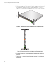
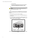
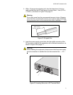
4. With a 14-gauge wire-stripping tool, strip the three wires in the tray
cable coming from the DC input power source to 8mm ± 1mm (0.31 in.,
± 0.039 in.), as shown in Figure 33 on page 71.
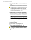
Warning
Do not strip more than the recommended amount of wire. Stripping
more than the recommended amount can create a safety hazard by
leaving exposed wire on the terminal block after installation. E10
Figure 33. Stripped Wire
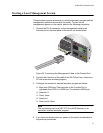
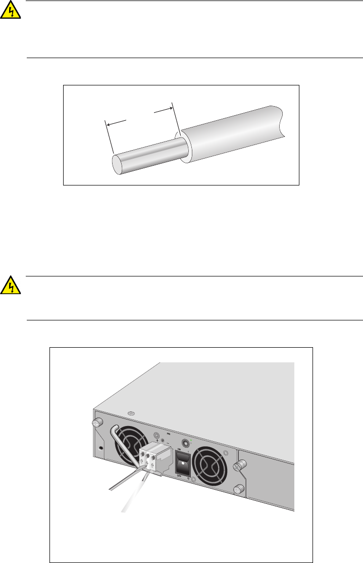
5. Insert the power supply ground wire into the middle connector of the
DC terminal and tighten the connection with a flathead screwdriver, as
shown in Figure 34 on page 71.
Warning
When installing this equipment, always ensure that the power supply
ground connection is installed first and disconnected last. E11
Figure 34. Inserting Wires into a DC Terminal Block
8mm ±1mm
(0.31in. ±0.039in.)
2269
FOR CENTRALIZED DC POWER
CONNECTION, INSTALL ON LY IN A
RESTRICTED AREA.
40-60VDC
6A
OUTPUT P
O
W
ER
F
A
U
LT
AT-PWR250R