


x510DP-52GTX Installation Guide
125
RJ-45 Twisted Pair Port Pinouts
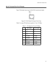
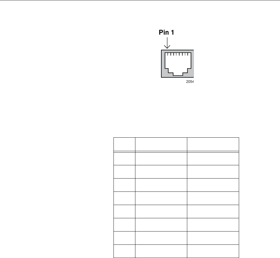
Figure 74 illustrates the pin layout of the RJ-45 connectors and ports.
Figure 74. RJ-45 Socket Pin Layout (Front View)
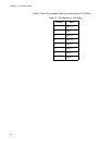
Table 11 on page 125 lists the pin signals for 10 and 100 Mbps.
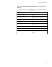
Table 11. Pin Signals for 10 and 100 Mbps
Pin MDI Signal MDI-X Signal
1TX+ RX+
2TX- RX-
3RX+ TX+
4 Not used Not used
5 Not used Not used
6RX- TX-
7 Not used Not used
8 Not used Not used