


Chapter 4: Installing the Switch and its Power Supplies
70
as this equipment.
Switching or disconnecting devices shall not be in the earthed
circuit conductor between the DC source and the point of
connection of the earthing electrode conductor.
E55
Warning
Enough wiring space is required to allow the conductors to be
introduced and connected easily.
E56
To power on a switch with a DC AT-PWR250R-80 Power Supply Module,
review the essential safety information above and perform the following
procedure:
1. Power off the DC circuit to be used for the chassis.
2. Verify that the On/Off switch on the DC AT-PWR250R-80 Module is in
the Off position.
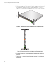
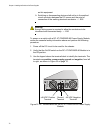
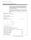
3. Use the legend above the terminal block to identify the terminals. The
terminals are positive, power supply ground and negative, from left
to right, as shown in Figure 32 on page 70.
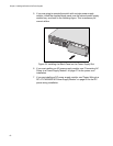
Figure 32. DC Terminal Block on the DC AT-PWR250R-80 Power Supply
Module
2205
A
A
AT-PWR250R
DC OUT
FAULT
+
-
6A
40-60VDC
FOR CENTRALIZED DC POWER
CONNECTION, INSTALL ONLY IN A
ON
OFF
+48 VDC Positive Ground -48 VDC Negative
TerminalTerminalTerminal