


Chapter 7: Cabling the Stacking Ports
96
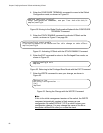
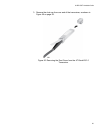
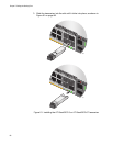
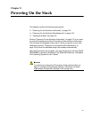
7. Position the transceiver with the release tab on the bottom and slide it
into the slot until it clicks into place, as shown in Figure 59 on page 96.
Figure 59. Installing the AT-StackXS/1.0 Transceiver in Slot S2
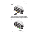
8. Repeat this procedure to connect additional switches to the stack with
AT-StackXS/1.0 transceivers.
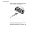
9. To create the redundant path with the ring topology shown in Figure 15
on page 42 and Figure 16 on page 43, connect a stacking cable to the
empty stacking slots on the top and bottom switches.
10. After connecting the stacking cables to all the switches, go to Chapter
8, “Powering On the Stack” on page 101.
S2
/28
S1/2
7
26
25
CON
SO
LE
SFP+
2685