


Chapter 2: Virtual Chassis Stacking
40
Stacking Port Topologies
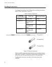
The switches of a stack are connected with the S1 and S2 ports and the
stacking transceivers shown in Figure 12 on page 38.
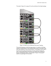
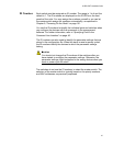
There are two wiring configurations. The first topology is called the linear
topology. In this topology the switches are connected with a single
pathway. A stacking transceiver in one switch is connected to a stacking
transceiver in the next switch, which is connected to the next switch, and
so on. The connections must crossover to different stacking slots on the
switches. The stacking transceiver in the S1 slot in one switch must
connect to the stacking transceiver in the S2 slot in the next switch.
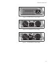
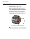
Figure 13 is an example of a stack of two switches in the linear topology.
The transceiver in the S1 slot on the top switch is connected to the
transceiver in the S2 slot on the bottom switch.
Figure 13. Stack of Two Switches in the Linear Topology
Caution
The stack will not function if the connections to the S1 and S2 slots
do not crossover on the switches. The switches will not form a stack
and instead operate as stand-alone devices.
2694
S2/28
S1/27
26
25
CONSOLE
SFP+
S2/28
S1/27
26
25
CONSOLE
SFP+