


Chapter 4: Installing the Switch and its Power Supplies
64
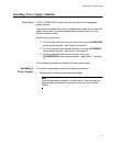
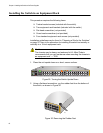
Installing the Switch in an Equipment Rack
This procedure requires the following items:
Twelve bracket screws (included with the switch)
Two equipment rack brackets (included with the switch)
Flat-head screwdriver (not provided)
Cross-head screwdriver (not provided)
Four standard equipment rack screws (not provided)
Installation guidelines may be found in “Choosing a Site for the Switches”
on page 52. Here is the procedure for installing the switch horizontally or
vertically in a 19-inch equipment rack.
Caution
The chassis may be heavy and awkward to lift. Allied Telesis
recommends that you get assistance when mounting the chassis in
an equipment rack. E28
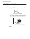
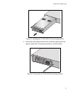
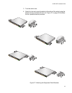
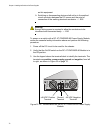
1. Place the unit upside down on a level, secure surface.
Figure 25. Turning the Switch Upside Down
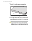
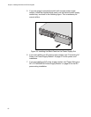
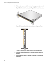
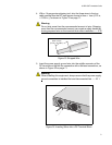
2. Using a flat-head screwdriver, pry the rubber feet from the bottom of
the switch, as shown in Figure 26.
Figure 26. Removing the Rubber Feet
2668
S2/52
S1/51
50
49
CONSOLE
x510DP-52GTX
SFP+
FDX HDX COL
1000 LINK ACT 10/100 LINK ACT
351791113151719
21 23
46810122 16 18 2014
22 24
27 2925 31 33 35 37 39 41 43 45 47
28 30 32 34 3626 40 42 4438
46 48
2669
x510DP-52GTX
3
5179
1
1
46
810
1
22