


Data Communications
22
Flow Control
The CodeWriter 4500 Series printers provide two methods to control the flow of data
between the host system and the printer. Hardware or Xon/Xoff flow control is
selected from the Operator Panel.
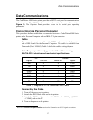
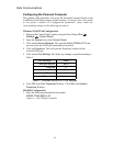
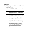
Hardware Flow Control
The printer uses the CTS, RTS, DTR, and DSR signals during hardware flow
control. Table 4 lists how the printer uses each signal.
Signal Function
CTS Input: The printer monitors the CTS signal for requests
from the host system to send data. This signal must be
asserted ON (Spacing, Positive Voltage) for the printer to
receive data.
RTS Output: The printer asserts this signal ON (Spacing,
Positive Voltage) whenever the printer is turned on. The
polarity of this signal may be changed from the Operator
Panel.
DTR Output: The printer asserts this signal ON (Spacing,
Positive Voltage) whenever it is ready to receive data. This
signal controls the flow of data from the host system.
When the printer’s input buffers have reached an almost
full level, the printer de-asserts the signal OFF (Marking,
Negative). In this condition host system should suspend
sending data. The polarity of this signal may be changed
from the Operator Panel.
DSR Input: The printer monitors the DSR signal to control
sending data to the host system. This signal must be
asserted ON (Spacing, Positive Voltage) for the printer to
send data. The CodeWriter 4500 Series printers depend
on data transmission to the host system for many
applications.
Table 4 - Hardware Flow Control Signal Functions