


Wiring and Connections
13
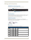
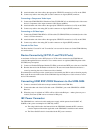
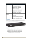
UDM-0404 Endeleo Multi-Format Distribution Hub
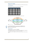
Excessive skew can adversely affect video image quality, especially at long cable lengths and
high signal resolutions.
UDM Hubs allow you to compensate brightness, sharpness and skew delay via options in the Status page
of the UDM’s built-in WebConsole (see the Video Compensation section on page 29).
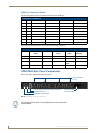
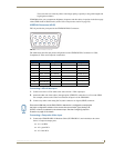
VIDEO IN Connectors (HD15)
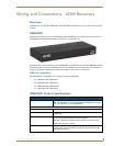
FIG. 10 provides the pin layout for the VIDEO IN HD15 Connectors:
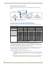
The table below describes the pinout configuration on the VIDEO IN HD15 connector for VGA,
Component, S-Video and Composite connections:
Connecting a VGA Video Input
1.
Connect one end of a VGA cable to the source device’s VGA output port.
2. Attach the other end of the cable to the appropriate VIDEO IN connection (A or B) on the UDM.
For example, connect to the Video In connection on Input A of the UDM-0404.
3. Connect any audio to the analog (RCA) audio connectors or digital (SPDIF) connector.
Connecting a Composite Video Input
1.
Connect the UDM-HD15RCA3 Breakout Cable (FG-HD15RCA3, not included) to the source
device’s Composite output ports:
A1 = red RCA
A2 = green RCA
A3 = blue RCA
FIG. 10 VIDEO IN HD15 Connector
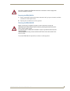
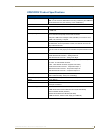
VIDEO IN HD15 Pinout Configuration
Input Pin VGA Component S-Video Composite
1 Red Y Luminance CVBS1
6 Red - Ground Y - Ground Luminance - Ground CVBS1 Ground
2 Green Pb - CVBS2
7 Green - Ground Pb - Ground - CVBS2 Ground
3 Blue Pr Chrominance CVBS3
8 Blue - Ground Pr - Ground Chrominance - Ground CVBS3 Ground
13 Horizontal Sync - - -
14 Vertical Sync - - -
12345
67891
1112131415
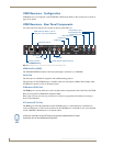
Ensure the UDM Hub port the RX01/RX02 is attached to is configured correctly within
the Hub’s configuration software. Also ensure the correct Audio Type (Analog L/R,
S/PDIF, or None) is selected for the relevant input. See the Configuring Inputs A-
D section on page 45 for details.